


8 9
TOOL ASSEMBLY
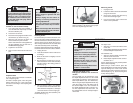
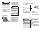
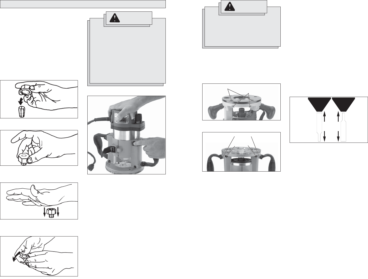
To remove collet from nut, hold nut fi rmly
with one hand and press the collet to one
side with the other hand (Fig. 4).
Collets
The collet must be attached to the collet nut
before it is put into the collet shaft. Be sure
that the size of the collet matches the size
of the bit shank being used. If the wrong
size bit shank is used, the collet may break.
For attaching or detaching the collet nut to
the collet, follow the illustrated instructions
on this page.
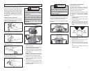
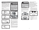
Attaching Collet to Collet Nut
To assemble, place the narrow end of the
collet on an even surface. Take the nut and
place it over the collet (Fig. 1).
Position nut squarely over collet with the
smaller opening of the nut facing up (Fig. 2).
Snap nut and collet together by fi rmly apply-
ing downward pressure into assembly with
palm of hand (Fig. 3).
WARNING
To reduce the risk of injury, always
unplug the tool before attaching or
removing accessories or making
adjustments.
Pressing the motor release button
will cause the motor housing to
drop down, which may cause per-
sonal injury or damage to the tool or
workpiece. Make sure your hand is
fi rmly on the motor when pressing
the button.
Fig. 1
Fig. 2
Fig. 3
Fig. 4
Fig. 5
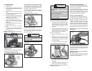
1. Unplug the tool. Make sure the locking
lever is fully open.
2. Align the depth adjustment screw on the
motor with the hole on the base.
3. Press and hold the motor release button
and lower the motor into the base to the
desired depth.
NOTE: The plunge base does not have
a motor release button. Release the
locking lever and pull out the motor.
4. Release the motor release button and
push in the locking lever to the fully
closed position.
5. To remove the motor, fully open the
locking lever, grasp the motor, press
and hold the motor release button, and
pull out the motor.
Installing/Removing Sub-bases
Fixed sub-bases (black):
To remove the sub-base, remove the
sub-base screws. To install the sub-base,
secure it with the sub-base screws.
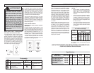
Adjustable sub-bases (clear):
To ensure the sub-base is centered, use the
centering cone and pin whenever tighten-
ing, adjusting, or changing the adjustable
sub-base.
1. Install the sub-base and screws, but do
not tighten them.
2. Lower the motor until the collet is about
1" above the base.
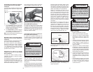
3. With the router upside down, insert the
pin into the cone, then into the collet (see
Fig. 8 for correct orientation). Tighten the
collet.
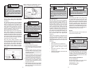
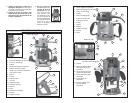
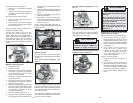
Installing/Removing Edge Guide
To install an edge guide, loosen the two rod
screws. Insert the edge guide rods into the
rod holes and tighten the rod screws.
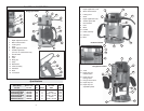
For Cat. Nos. 5615, 5616 and 5619 Series,
see Fig. 6:
Fig. 6
Rod holes
Rod screws
For Cat. No. 5625 Series, see Fig. 7:
Fig. 7
Rod holes
Rod screws
Fig. 8
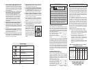
For
1/4"
Collets
For
1/2"
Collets
Into
Cone
Into
Collet
Installing/Removing the Motor
WARNING
To reduce the risk of injury, DO NOT
use the router if the locking lever
does not hold the motor securely in
the base. If the locking lever becomes
loose, contact a MILWAUKEE service
facility for repairs.
4. Push the cone down fi rmly. The sub-
base will center.
5. While pressing down on the cone,
tighten the sub-base screws.
6. Remove the centering pin from the
collet. Save the pin and cone for future
use.
7. To remove the sub-base, remove the
sub-base screws.