


10 11
WARNING
To reduce the risk of injury, wear
safety goggles or glasses with side
shields. Always wait for the bit to
stop completely and unplug the tool
before changing accessories or mak-
ing adjustments. Never make adjust-
ments while the router is running. Do
not defeat the guards.
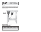
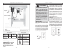
Do not use this router unless it is se-
curely installed into a recommended
JessEm router lift and table.
OPERATION
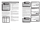
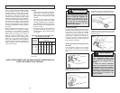
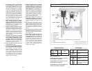
Using the Variable Speed Dial
The variable speed dial allows the user to
adjust the rotating speed (RPM) of the tool.
Variable speed dial settings range from
numbers (7) seven through (1) one. Higher
numbers correspond to higher speeds and
lower number correspond to lower speeds.
To change the speed, set the variable speed
control dial to the desired number.
Use the following chart to determine the best
speed for the bit diameter.
Starting and Stopping Motor
1. To start the motor, lift up the On/Off
switch. The switch will stay up until it is
pushed down.
2. To stop the motor, push down the On/Off
switch.
3. To lock the motor, pull out the lock key.
With the lock key removed, the On/Off
switch will not turn on the motor when
lifted up. However, if the lock key is
removed when the motor is on, pushing
down the on/off switch will still turn off
the motor.
Electronic Overload Protection
Before the motor is overloaded, the elec-
tronic overload protection circuit will turn
off the tool.
If the motor shuts off during use, push down
the On/Off switch. Wait at least three (3)
seconds. This will reset the electronics in
the tool. Lift up the On/Off switch to con-
tinue use.
Soft Start
The Soft-Start feature reduces the amount
of torque reaction to the tool. This feature
gradually increases the motor speed up
from zero to the speed set by the variable
speed dial.
Feedback Control
The electronic speed control system allows
the tool to maintain constant speed between
no-load and load conditions.
Making the Cut
The speed and depth of cut will depend
largely on the type of material being worked.
Keep the cutting pressure constant but do
not use excessive force so the motor speed
slows excessively. It may be necessary on
exceptionally hard woods or problem materi-
als to make more than one pass to get the
desired depth of cut.
Before beginning the cut on the actual work-
piece, it is advisable to take a sample cut on
a scrap piece of lumber. This will show you
exactly how the cut will look as well as enable
you to check dimensions.
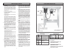
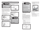
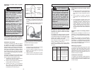
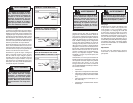
Position the fence so that the workpiece
feeds against the cutter rotation. Feeding
the workpiece with the cutter rotation is
called climb cutting, which is very dangerous.
Climb cutting can result in the workpiece
being thrown violently out of your control at
great speed.
WARNING
To reduce the risk of injury, avoid
“climb cutting.” Climb cutting can
cause the workpiece to be thrown
violently out of your control. Even
small router bits can cause in climb
cutting.
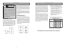
Speed
setting
1
2
3
4
5
6
7
RPM
10,000
12,000
14,000
16,000
18,000
20,000
22,000
Max. Bit
Diameter
3" to 3-1/2"
3" to 3-1/2"
2-1/4" to 2-1/2"
2-1/4" to 2-1/2"
1-1/4" to 2"
1"
1"
Fence
Direction
of Feed
Direction
of Rotation
WRONG! CLIMB CUTTING
Fence
Fence
Direction
of Rotation
Direction
of Rotation
Direction of Feed
CORRECT! FEED AGAINST
CUTTER ROTATION.
CAUTION! CLIMB CUTTING COULD
OCCUR IF CUTTING COMPLETELY
THROUGH THE STOCK.
Direction
of Feed
WARNING
To reduce the risk of injury, always
use feather boards, push sticks or
push blocks with proper guarding.
Keep hands away from moving bit.
Refer to the Router Table manual for
proper table setup and use.