


page 6
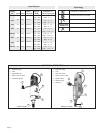
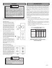
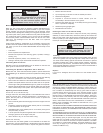
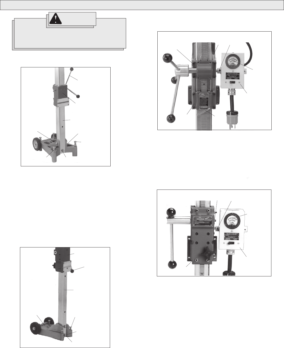
Fig. 4
Socket
screw
Ammeter
gauge
Meter
box
Socket screw
and washer
Cradle
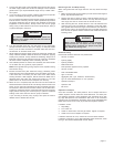
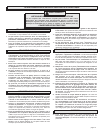
Moving the Handle to the Other Side
For Cat. Nos. 4125 & 4130 only (Fig. 3).
WARNING!
TOOL ASSEMBLY
To reduce the risk of injury, always unplug tool
before attaching or removing accessories or mak-
ing adjustments. Use only specifically recom-
mended accessories. Others may be hazardous.
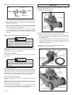
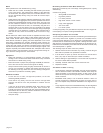
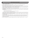
Assembling Dymorigs & Vac-U-Rig® Stands
For Cat. No. 4125 & 4130 only (Fig. 1).
1. Set the base on the ground. Loosen the hex bolt and nut (wrench
not supplied). Raise the column upright.
2. To core vertically or horizontally, insert the large column bolt
(provided in separate accessory bag) through the bottom of column
and into the base. Tighten hex bolt and nut (wrench not supplied).
To angle core, tilt the column to the desired angle and tighten the
hex bolt and nut. Save the column bolt for future use when vertical
or horizontal coring.
3. Tighten the two (2) black socket set screws located on the base
with the supplied wrench.
4. Screw the four (4) handle spokes (provided in separate accessory
bag) into the hub on the cradle assembly.
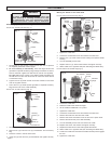
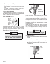
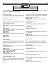
For Cat. No. 4115 & 4120 only (Fig. 2).
1. Set the base on the ground.
2. Remove two (2) bolts and two (2) lockwashers from accessory
bag.
3. Place the column in the slot of the base.
4. Insert two (2) bolts and two (2) lockwashers and tighten securely.
Fig. 2
Cradle
assembly
Handle
spoke
Column
Base
Leveling
screws (4)
Column
bolts (2)
Lock washers
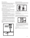
Fig. 3
Socket
screws (4)
Bubble
level
Socket
screw
Ammeter
gauge
Meter
box
Cradle
lock
Cradle
1. Tighten the cradle lock.
2. Loosen the socket head screw and remove the meter box.
3. Remove four (4) socket head screws holding the spoked handle
housing.
4. Turn the assembly around 180°.
5. Replace the four (4) socket head screws and tighten securely.
6. Attach meter box to opposite side (see "Mounting the Meter Box").
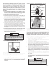
For Cat. Nos. 4115 & 4120 only (Fig. 4).
1. Loosen the cradle lock.
2. Raise the cradle to the maximum height.
3. Lift the cradle an additional 1/2" by hand.
4. Tighten the cradle lock.
5. Loosen the socket head screw and remove the meter box.
6. Remove the meter box stud from the cradle.
7. Remove the screw and washer from the end of the pinion shaft.
8. Remove the handle and pinion shaft assembly.
9. Turn the assembly around 180° and insert into cradle.
10. Replace the screw and washer and tighten securely.
11. Replace the meter stud on the side opposite the handle.
12. Attach meter box to opposite side (see “Mounting the Meter Box”).
13. Loosen the cradle lock and lower the cradle until the pinion engages
the rack.
14. Tighten the cradle lock.
Fig. 1
Handle
spoke
Cradle
assembly
Column
Base
Leveling
screws (4)
Column bolts
Socket set
screws (2)
Hex bolt