


4
5
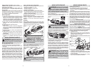
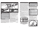
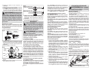
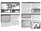
1. Side handle
2. Spindle lock
3. Side handle socket
4. Paddle switch
5. Switch lock-on
6. Switch lock-off
7. Type 27 guard
8. Guard lock lever
9. Trigger switch
10.Slide switch
Safety Warnings Specific for Grinding and
Abrasive Cutting-Off Operations:
• Use only wheel types that are recommended
for your power tool and the specifi c guard
designed for the selected wheel. Wheels for
which the power tool was not designed can not
be adequately guarded and are unsafe.
• The guard must be securely attached to the
power tool and positioned for maximum safety,
so the least amount of wheel is exposed to-
wards the operator. The guard helps to protect
operator from broken wheel fragments and ac-
cidental contact with wheel.
• Wheels must be used only for recommended
applications. For example: do not grind with the
side of cut-off wheel. Abrasive cut-off wheels are
intended for peripheral grinding, side forces applied
to these wheels may cause them to shatter.
• Always use undamaged wheel fl anges that are
of correct size and shape for your selected
wheel. Proper wheel fl anges support the wheel
thus reducing the possibility of wheel breakage.
Flanges for cut-off wheels may be different from
grinding wheel fl anges.
• Do not use worn down wheels from larger
power tools. Wheel intended for larger power tool
is not suitable for the higher speed of a smaller
tool and may burst.
Additional Safety Warnings Specifi c for Abra-
sive Cutting-Off Operations:
• Do not "jam" the cut-off wheel or apply ex-
cessive pressure. Do not attempt to make an
excessive depth of cut. Overstressing the wheel
increases the loading and susceptibility to twisting
or binding of the wheel in the cut and the possibility
of kickback or wheel breakage.
• Do not position your body in line with and
behind the rotating wheel. When the wheel, at
the point of operation, is moving away from your
body, the possible kickback may propel the spin-
ning wheel and the power tool directly at you.
• When wheel is binding or when interrupting a
cut for any reason, switch off the power tool
and hold the power tool motionless until the
wheel comes to a complete stop. Never attempt
to remove the cut-off wheel from the cut while
the wheel is in motion otherwise kickback may
occur. Investigate and take corrective action to
eliminate the cause of wheel binding.
• Do not restart the cutting operation in the
workpiece. Let the wheel reach full speed and
carefully reenter the cut. The wheel may bind,
walk up or kickback if the power tool is restarted
in the workpiece.
• Support panels or any oversized workpiece to
minimize the risk of wheel pinching and kick-
back. Large workpieces tend to sag under their
own weight. Supports must be placed under the
workpiece near the line of cut and near the edge
of the workpiece on both sides of the wheel.
• Use extra caution when making a "pocketcut"
into existing walls or other blind areas. The
protruding wheel may cut gas or water pipes, elec-
trical wiring or objects that can cause kickback.
Safety Warnings Specifi c for Sanding Operations:
• Do not use excessively oversized sanding disc
paper. Follow manufacturers recommenda-
tions, when selecting sanding paper. Larger
sanding paper extending beyond the sanding
pad presents a laceration hazard and may cause
snagging, tearing of the disc or kickback.
Safety Warnings Specifi c for Wire Brushing
Operations:
• Be aware that wire bristles are thrown by the
brush even during ordinary operation. Do not
over stress the wires by applying excessive
load to the brush. The wire bristles can easily
penetrate light clothing and/or skin.
• If the use of a guard is recommended for wire
brushing, do not allow any interference of the
wire wheel or brush with the guard. Wire wheel
or brush may expand in diameter due to workload
and centrifugal forces.
Additional Safety Warnings
• Maintain labels and nameplates. These carry
important information. If unreadable or missing,
contact a MILWAUKEE service facility for a free
replacement.
• WARNING: Some dust created by power sanding,
sawing, grinding, drilling, and other construction
activities contains chemicals known to cause
cancer, birth defects or other reproductive harm.
Some examples of these chemicals are:
• lead from lead-based paint
• crystalline silica from bricks and cement and other
masonry products, and
• arsenic and chromium from chemically-treated
lumber.
Your risk from these exposures varies, depending
on how often you do this type of work. To reduce
your exposure to these chemicals: work in a well
ventilated area, and work with approved safety
equipment, such as those dust masks that are spe-
cially designed to fi lter out microscopic particles.
9
10
5
Double Insulated
Volts Alternating Current
Volts Alternating Current /
Direct Current
Amps
Revolutions per Minute (RPM)
Underwriters Laboratories, Inc.
United States and Canada
Mexican Approvals Marking
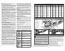
FUNCTIONAL DESCRIPTION
SYMBOLOGY
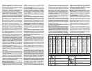
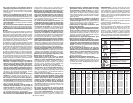
SPECIFICATIONS
Cat. No. Volts Amps RPM
Spindle
Thread Size
Wheel
Size
Switch
Type
Lock-On
Guard
Type
Speed
Dial
6117-30
6117-31
6117-31B
6117-33
6117-33D
6121-30
6121-31
6121-31A
6124-30
6124-31
6146-30
6146-31
6146-33
6147-30
6147-31
6161-30
6161-31
6161-33
120 AC
120 AC
120 AC
120 AC
120 AC
120 AC
120 AC
120 AC/DC
120 AC
120 AC
120 AC
120 AC
120 AC
120 AC
120 AC
120 AC
120 AC
120 AC
13
13
13
13
13
11
11
11
13
13
11
11
11
11
11
13
13
13
11,000
11,000
11,000
11,000
2,800-11,000
11,000
11,000
11,000
9,000
9,000
11,000
11,000
11,000
11,000
11,000
9,000
9,000
9,000
5/8"-11
5/8"-11
5/8"-11
5/8"-11
5/8"-11
5/8"-11
5/8"-11
5/8"-11
5/8"-11
5/8"-11
5/8"-11
5/8"-11
5/8"-11
5/8"-11
5/8"-11
5/8"-11
5/8"-11
5/8"-11
5"
5"
5"
5"
5"
4½"
4½"
5"
6"
6"
4½"
4½"
4½"
4½"
4½"
6"
6"
6"
Paddle
Paddle
Paddle
Slide
Slide
Trigger
Trigger
Trigger
Trigger
Trigger
Paddle
Paddle
Slide
Paddle
Paddle
Paddle
Paddle
Slide
Yes
No
No
Yes
Yes
Yes
No
No
Yes
No
Yes
No
Yes
Yes
No
Yes
No
Yes
Type 27
Type 27
Type 27
Type 27
Type 27
Type 27
Type 27
Type 27
Type 27
Type 27
Type 27
Type 27
Type 27
Type 27
Type 27
Type 1
Type 1
Type 1
No
No
No
No
Yes
No
No
No
No
No
No
No
No
No
No
No
No
No
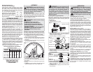
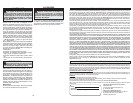
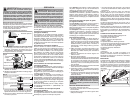
outlet (See Figure A). If the tool should electrically
malfunction or break down, grounding provides a
low resistance path to carry electricity away from
the user, reducing the risk of electric shock.
The grounding prong in the plug is connected
through the green wire inside the cord to the
grounding system in the tool. The green wire in the
cord must be the only wire connected to the tool's
grounding system and must never be attached to an
electrically "live" terminal.
Your tool must be plugged into
an appropriate outlet, properly
installed and grounded in ac-
cordance with all codes and
ordinances. The plug and outlet
should look like those in Figure A.
Fig. A
GROUNDING
WARNING Improperly connecting the
grounding wire can result in the risk of
electric shock. Check with a qualifi ed electri-
cian if you are in doubt as to whether the
outlet is properly grounded. Do not modify
the plug provided with the tool. Never remove
the grounding prong from the plug. Do not
use the tool if the cord or plug is damaged. If
damaged, have it repaired by a MILWAUKEE
service facility before use. If the plug will not
fi t the outlet, have a proper outlet installed by
a qualifi ed electrician.
Grounded Tools: Tools with Three Prong Plugs
Tools marked "Grounding Required" have a three
wire cord and three prong grounding plug. The
plug must be connected to a properly grounded
1
4
5
6
8
7
3
2