


6
7
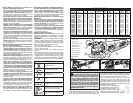
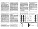
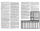
Grounded tools require a three wire extension
cord. Double insulated tools can use either a two
or three wire extension cord. As the distance from
the supply outlet increases, you must use a heavier
gauge extension cord. Using extension cords with
inadequately sized wire causes a serious drop in
voltage, resulting in loss of power and possible tool
damage. Refer to the table shown to determine the
required minimum wire size.
The smaller the gauge number of the wire, the
greater the capacity of the cord. For example, a 14
gauge cord can carry a higher current than a 16
gauge cord. When using more than one extension
cord to make up the total length, be sure each cord
contains at least the minimum wire size required. If
you are using one extension cord for more than one
tool, add the nameplate amperes and use the sum
to determine the required minimum wire size.
Guidelines for Using Extension Cords
• If you are using an extension cord outdoors, be sure
it is marked with the suffi x "W-A" ("W" in Canada)
to indicate that it is acceptable for outdoor use.
• Be sure your extension cord is properly wired
and in good electrical condition. Always replace a
damaged extension cord or have it repaired by a
qualifi ed person before using it.
• Protect your extension cords from sharp objects,
excessive heat and damp or wet areas.
READ AND SAVE ALL
INSTRUCTIONS FOR
FUTURE USE.
Recommended Minimum Wire Gauge
for Extension Cords*
Extension Cord Length
* Based on limiting the line voltage drop to
fi ve volts at 150% of the rated amperes.
Nameplate
Amperes
0 - 2.0
2.1 - 3.4
3.5 - 5.0
5.1 - 7.0
7.1 - 12.0
12.1 - 16.0
16.1 - 20.0
25'
18
18
18
18
16
14
12
75'
18
18
16
14
12
10
100'
18
16
14
12
10
150'
16
14
12
12
50'
18
18
18
16
14
12
10
EXTENSION CORDS
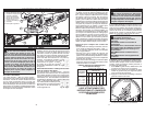
Installing Side Handle
The side handle may be installed on either side
of the gear case. Position the side handle in the
location which offers best control and guard protec-
tion. To install, thread side handle into side handle
socket and tighten securely.
WARNING To reduce the risk of injury,
always unplug tool before attaching
or removing accessories or making adjust-
ments. Use only specifi cally recommended
accessories. Others may be hazardous.
WARNING To reduce the risk of injury
when grinding:
• ALWAYS use the proper guard.
• ALWAYS properly install the guard.
• ALWAYS hold the tool fi rmly with both
hands using the handles provided before
and during grinding.
• NEVER use a wheel that has been dropped.
• NEVER bang grinding disc onto work.
• NEVER grind without proper safety
equipment.
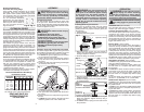
Tab
slots
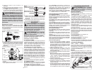
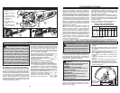
Installing, Removing and Adjusting the Guard
This tool is shipped with a guard. The guard must
be used when using the tool as a grinder. The guard
may be removed when using tool as a sander.
1. To remove the guard, unplug tool and remove
any accessories from spindle.
2. Press in the lock lever and rotate the guard to
line up the tabs on the grinder with the slots in
the guard.
3. Press in the lock lever and lift the guard straight
up and away from the tool.
Fig. 1
Detent slots
4. To install the guard, unplug the tool and remove
any accessories from the spindle.
5. Line up the tabs on the grinder with the slots in
the guard.
6. Press in the lock lever and press the guard onto
the tool.
7. To adjust the guard, press in the lock lever and
rotate the guard to one of fi ve detent slots.
Installing/Removing Accessories
Make sure the grinding wheel does not extend
beyond the bottom of the guard. Threaded hub
grinding wheels may require a deeper guard (see
"Accessories").
1. Unplug the tool.
2. Properly position the guard.
WARNING Only use accessories with
Maximum Safe Operating Speed rated at
least equal to the maximum speed marked
on the power tool. This speed is based on
the strength of the wheel, allowing for a
reasonable measure of safety. It is not meant
to imply a best or most effi cient operating
speed. Do not exceed the Maximum Safe
Operating Speed.
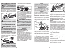
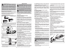
Fig. 2
Operator's Zones
3. Wipe the flange, flange nut and spindle to
remove dust and debris. Inspect the parts for
damage. Replace if needed.
4. Place the fl ange on spindle, as shown.
Spindle
Flange
Grinding
wheel
Flange nut
Fig. 3
ASSEMBLY
Flange nut
position for
1/8" thick or less wheels
Fig. 4
1/8"
1/4"
5. Place the selected wheel on the spindle and align
it with the fl ange.
6. Position the fl ange nut over the spindle according
to wheel thickness.
7. Press in the spindle lock button while turning the
fl ange nut clockwise. Tighten securely using a
spanner wrench.
8. To remove wheel, unplug the tool and reverse
the procedure.
Flange nut
position for
1/4" thick or more wheels
Fig. B
Fig. C
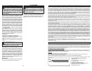
Double Insulated Tools:
Tools with Two Prong Plugs
Tools marked "Double Insulated" do not require
grounding. They have a special double insula-
tion system which satisfi es OSHA requirements
and complies with the applicable standards
of Underwriters Laboratories,
Inc., the Canadian Standard
Association and the National
Electrical Code. Double Insulated
tools may be used in either of
the 120 volt outlets shown in
Figures B and C.
WARNING To reduce the risk of injury,
wear safety goggles or glasses with side
shields.
WARNING To reduce the risk of injury,
always unplug tool before attaching
or removing accessories or making adjust-
ments. Use only specifi cally recommended
accessories. Others may be hazardous.
Controlled Start (some models)
The controlled start feature reduces the torque
reaction "jerk" when its trigger is pulled.
Constant Speed Tachometer (some models)
The constant speed tachometer keeps the tool's
revolutions per minute at an almost constant
speed even under load. The tachometer also helps
prevent tool overheating. The tool switches itself
off automatically when the motor is overloaded. If
this happens, release the trigger to reset. Pull the
trigger and continue work.
Electric Brake (some models)
The electric brake engages when the trigger is
released, causing the wheel to stop and allowing
you to proceed with your work. Generally, the wheel
stops within six seconds. However, there may be
a delay between the time you release the trigger
and when the brake engages. Occasionally the
brake may miss completely. If the brake misses fre-
quently, the saw needs servicing by an authorized
MILWAUKEE service facility. Make sure the tool
comes to a complete stop before laying it down.
Slide Switch Operation (some models)
To start the tool, grasp the handle and side handle
fi rmly and slide the switch to ON.
To stop the tool, release the switch. Make sure
the tool comes to a complete stop before laying
the tool down.
To lock-on the switch, slide the switch to ON and
press down on the front of the switch. To stop the
tool, press and release the switch. Make sure
the tool comes to a complete stop before laying
it down.
To vary the speed (6117-33D only), set the speed
dial from "1" (2,800 RPM) to "6" (11,000 RPM).
Paddle Switch Operation (some models)
To start the tool, grasp the handle and side handle
fi rmly. Pull the lock-off button back and squeeze
the paddle switch.
To stop the tool, release the paddle switch. Make
sure the tool comes to a complete stop before lay-
ing the tool down.
To lock-on the switch (some models), start the tool
and push in the lock-on button. To stop the tool,
squeeze and release the paddle switch. Make sure
the tool comes to a complete stop before laying
the tool down.
OPERATION