


10
Wiring
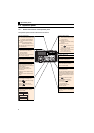
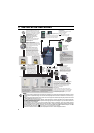
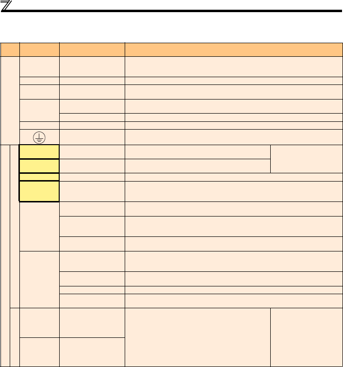
2.3.2 Terminal specifications
Type
Terminal
Symbol
Terminal Name Description
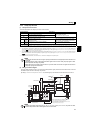
Main circuit
R/L1, S/L2,
T/L3 *
AC power input
Connect to the commercial power supply. Keep these terminals open when using the high
power factor converter (FR-HC) or power regeneration common converter (FR-CV).
When using single-phase power input, terminals are R/L1 and S/L2.
U, V, W Inverter output Connect a three-phase squirrel-cage motor.
P/+, PR Brake resistor connection
Connect a brake resistor (MRS type, MYS type, FR-ABR) across terminals P/+ and PR.
(The brake resistor can not be connected to the 0.1K or 0.2K)
P/+, N/-
Brake unit connection
Connect the brake unit (FR-BU2), power regeneration common converter (FR-CV) or high
power factor converter (FR-HC).
DC power input
Connect the plus side of the power supply to terminal P/+ and minus side to terminal N/-.
P/+, P1 DC reactor connection Remove the jumper across terminals P/+ and P1 and connect a DC reactor.
Earth (Ground)
For earthing (grounding) the inverter chassis. Must be earthed (grounded).
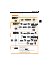
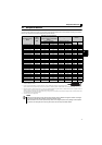
Control circuit/input signal
Contact input
STF Forward rotation start
Turn ON the STF signal to start forward rotation and turn it OFF
to stop.
When the STF and STR
signals are turned ON
simultaneously, the stop
command is given.
STR Reverse rotation start
Turn ON the STR signal to start reverse rotation and turn it OFF
to stop.
RH, RM, RL Multi-speed selection Multi-speed can be selected according to the combination of RH, RM and RL signals.
RES Reset
Used to reset alarm output provided when protective circuit is activated. Turn ON the RES
signal for more than 0.1s, then turn it OFF. Initial setting is for reset always. By setting Pr. 75,
reset can be set to enabled only at fault occurrence. Recover about 1s after reset is cancelled.
SD
Contact input common
(sink) (initial setting)
Common terminal for contact input terminal (sink logic) and terminal FM.
External transistor
common (source)
Connect this terminal to the power supply common terminal of a transistor output (open
collector output) device, such as a programmable controller, in the source logic to avoid
malfunction by undesirable current.
24VDC power supply
common
Common output terminal for 24VDC 0.1A power supply (PC terminal).
Isolated from terminals 5 and SE.
PC
External transistor
common
(sink) (initial setting)
Connect this terminal to the power supply common terminal of a transistor output (open
collector output) device, such as a programmable controller, in the sink logic to avoid
malfunction by undesirable current.
Contact input common
(source)
Common terminal for contact input terminal (source logic).
24VDC power supply
Can be used as 24VDC 0.1A power supply.
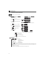
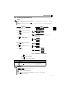
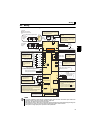
Safety stop input terminal
common
Common terminal for safety stop input terminals S1 and S2.
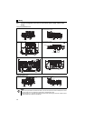
Safety stop function *
S1
Safety stop input
(Channel 1)
S1/S2 are safety stop signals for use with in conjunction with
an approved external safety unit. Both S1/S2 must be used in
dual channel form. Inverter output is shutoff depending on
shorting/opening between S1 and PC, S2 and PC.
In the initial status, terminal S1 and S2 are shorted with
terminal PC by shorting wire.
Remove the shorting wire and connect the safety relay module
when using the safety stop function.
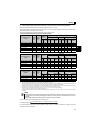
Input resistance 4.7k
Voltage when contacts are
open
21 to 26VDC
When contacts are short-
circuited
4 to 6mADC
S2
Safety stop input
(Channel 2)
For more details, refer to the Safety stop function instruction manual (BCN-A211508-004). (Refer to the front cover for how to obtain the manual.)