


12
Wiring
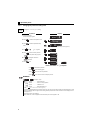
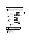
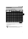
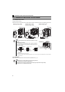
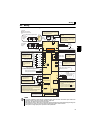
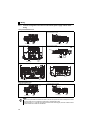
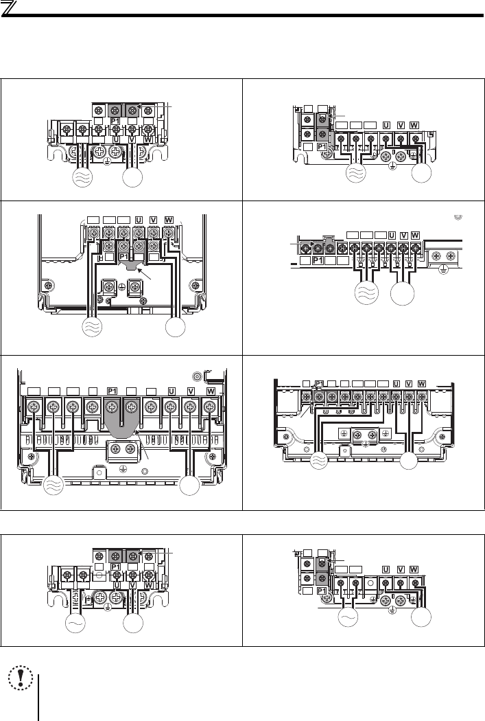
2.3.3 Terminal arrangement of the main circuit terminal, power supply and the motor
wiring
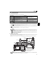
Three-phase 200V/400V class
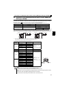
Single-phase 200V class
FR-E720-0.1KSC to 0.75KSC FR-E720-1.5KSC to 3.7KSC
FR-E740-0.4KSC to 3.7KSC
FR-E720-5.5KSC, 7.5KSC FR-E740-5.5KSC, 7.5KSC
FR-E720-11KSC, 15KSC FR-E740-11KSC, 15KSC
FR-E720S-0.1KSC to 0.4KSC FR-E720S-0.75KSC to 2.2KSC
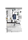
NOTE
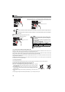
Make sure the power cables are connected to the R/L1, S/L2, and T/L3. (Phase need not be matched.) Never connect
the power cables to the U, V, and W of the inverter. Doing so will damage the inverter.
Connect the motor to U, V, and W. Turning ON the forward rotation switch (signal) at this time rotates the motor
counterclockwise when viewed from the load shaft.
MotorPower supply
N/-
P/+ PR
IM
R/L1 S/L2 T/L3
Jumper
Motor
Power supply
N/-
P/+
PR
IM
R/L1 S/L2 T/L3
Jumper
Motor
Power supply
IM
N/-
P/+
PR
R/L1 S/L2 T/L3
Jumper
N/-
P/+
PR
R/L1 S/L2 T/L3
MotorPower supply
Jumper
IM
N/-
P/+
PR
R/L1 S/L2 T/L3
Jumper
MotorPower supply
IM
Motor
Power supply
IM
N/-
P/+
PR
R/L1 S/L2 T/L3
Jumper
MotorPower supply
N/-
P/+ PR
IM
R/L1 S/L2
Jumper
Motor
Power supply
N/-
P/+
PR
IM
R/L1 S/L2
Jumper