


17
2
Wiring
2.3.5 Safety stop function
(1) Description of the function
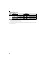
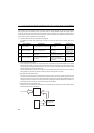
The terminals related to the safety stop function are shown below.
In the initial status, terminal S1 and S2 are shorted with terminal PC by shortening wire. Remove the shortening wire and connect the safety relay module
when using the safety stop function.
In the initial setting, output frequency detection (FU signal) is assigned to terminal FU. Set "80" to Pr.191 FU terminal function selection to assign SAFE signal.
The function can be assigned to other terminals by setting "80 (positive logic) or 180 (negative logic)" to any of Pr.190 to Pr.192 (Output terminal function
selection). ( Refer to the Instruction Manual (Applied))
In the initial setting, inverter running (RUN signal) is assigned to terminal RUN. Set "81" to Pr.190 RUN terminal function selection to assign SAFE2 signal. The
function can be assigned to other terminals by setting "81 (positive logic) or 181 (negative logic)" to any of Pr.190 to Pr.192 (Output terminal function selection).
( Refer to the Instruction Manual (Applied))
At an internal safety circuit failure, one of E.SAF, E.6, E.7, and E.CPU is displayed on the operation panel.
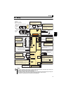
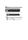
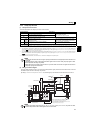
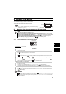
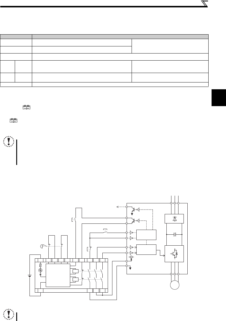
(2) Wiring connection diagram
To prevent restart at fault occurrence, connect terminals RUN (SAFE 2 signal) and SE to terminals XS0 and XS1, which are
the feedback input terminals of the safety relay module.
By setting Pr. 190 RUN terminal function selection = "81 (SAFE2 signal)", terminal RUN is turned OFF at fault occurrence.
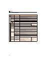
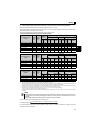
Terminal Symbol Description
S1
For input of safety stop channel 1.
Between S1 and PC / S2 and PC
Open: In safety stop state.
Short: Other than safety stop state.
S2
For input of safety stop channel 2.
PC
Common terminal for terminal S1 and S2.
FU
SAFE
signal
Outputs the safety stop status
The signal is output when inverter output is shut off due to the
safety stop function.
OFF: Drive enabled or drive stop (at an internal
safety circuit failure
)
ON: Drive stop (no internal safety circuit failure
)
RUN
SAFE2
signal
Outputs when an alarm or failure is detected.
The signal is output when no internal safety circuit failure
exists.
OFF: Internal safety circuit failure
ON : No internal safety circuit failure
SE Common terminal for open collector outputs (terminal RUN and FU)
NOTE
Hold the ON or OFF status for 2ms or longer to input signal to terminal S1 or S2. Signal input shorter than 2ms is not
recognized.
Use SAFE signal to monitor safety stop status. SAFE signal cannot be used as safety stop input signal to other
devices (other than the safety relay module).
SAFE 2 signal can only be used to output an alarm or to prevent restart of an inverter. The signal cannot be used as
safety stop input signal to other devices.
NOTE
Changing the terminal assignment using Pr. 190 to Pr. 192 (output terminal function selection) may affect the other
functions. Set parameters after confirming the function of each terminal.
S2
S1
PC
Inverter
START/RESET
+24V
QS90SR2SN-Q
K1
X0 X1
COM0
COM1
24G
XS0
XS1
Z10
Z00
Z20
Z11 Z01 Z21
K2
DC24V
RUN(SAFE2)
R S T
U V W
MITSUBISHI MELSEC Safety relay module
IM
SE
STF
STR(STOP)
STF
STOP
SD
I/O control
FU(SAFE)
monitor
*1
*1
*2
*2
Internal
Safety
Circuit
Output shutoff
circuit
*1 Output signals differ by the setting of Pr.190 and
Pr.191 (Output terminal function selection).
*2 Input signals differ by the setting of Pr178 to Pr.182
(Input terminal function selection).
Emergency
stop button