


ASSEMBLY INSTRUCTIONS/OPERATIONS
8FP FLOOR PLANER SERIES OPERATION AND PARTS MANUAL REV #2 (05/28/09) PAGE 21
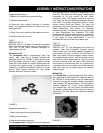
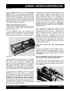
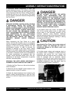
FIGURE 13
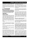
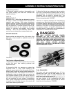
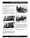
The most widely used drum is of the two-section
design. FIGURE 14. It incorporates two half sectioned
side plates that are positioned on the center shaft to
facilitate optimum flail spacing. The half side plate
sections also provide additional stability and structural
rigidity for the drum rods. The two-section drum can
accommodate the use of all flail designs while meeting
the most demanding job applications.
General Notes Regarding Flail Drums
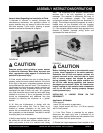
1) Flail drum rods are held in position by end caps and
related fasteners. The end caps are heat treated to
extend their service life.
2) The countersunk Allen head capscrews are
retained to the flail drum by both self locking, hexa
gon
head nuts and lock washers. The lock washers
provide additional redundancy while eliminating open,
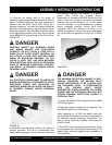
FIGURE 14
exposed threads that can become worn or damaged
from field use. A countersunk Allen head capscrew
was chosen over a conventional hexagon head
capscrew to eliminate anticipated wear. Component
wear would substantially increase the difficulty of
disassembling drum components in the field. Before
removing these capscrews, clean the internal hexagon
with an appropriate tool to help facilitate their removal.
3) Flail rods are not intended to rotate in the drum
assembly while the Floor Pla
ner is in operation.
Severe operation can cause the drum plates to wear
and elongate. Drum rods are also subject to wear and
elongation. If the total amount of wear is not severe,
various types of high strength, anaerobic adhesives
can be utilized to secure the rods to the drum. Severe
component wear is always an immediate reason to
reject either the rods and/or drum and replace with
factory approved, replacement parts.
4) Regularly inspect the drum for excessive wear and
signs of fatigue. Random vibration caused by the
planing process is difficult, if not impossible, to fully
predict. Component service life is impossible to
predict. Work surface materi
als, operator techniques
and general maintenance are also contributing factors
that will limit the service life of the drum and/or
components. If there is any question regarding the
structural integrity of a drum or any component,
properly discard and replace with factory approved,
replacement parts.
5) It is advisable to always have a minimum of one
spare, loaded drum available to increase job site
productivity and reduce down time. Replacing worn
flails is a job that can require from only a few, short
minutes to even hours for extremely worn and
damaged components. Repl
acing a drum on the
driveshaft can usually be accomplished in a matter of
a few minutes. It is a common practice to replace worn
flails during normal, unproductive time and keep a
number of loaded, replacement drums on the job site
to speed production rates.
INSTALLING FLAILS ON THE TWO SECTION
DRUM.
All flails are assembled on the two section drum in
sequence patterns with the spacer washers. Spacer
washers provide for an overlapping effect of the flails
that produces consistent material removal from the
work surface.
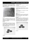
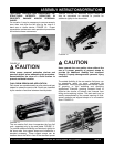
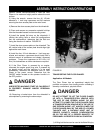
Normal installation procedure (fine finish) for star,
beam and all 1/8-inch nominal thickness flails
1) Install a flail next to the outside side plate of the
narrow section. Next, install a spa
cer washer. Follow
with a flail and continue the sequence until the section
is full. FIGURE 15.
FIGURE 15