


ASSEMBLY INSTRUCTIONS/OPERATIONS
8FP FLOOR PLANER SERIES OPERATION AND PARTS MANUAL REV #2 (05/28/09) PAGE 37
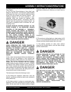
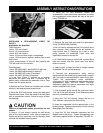
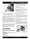
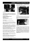
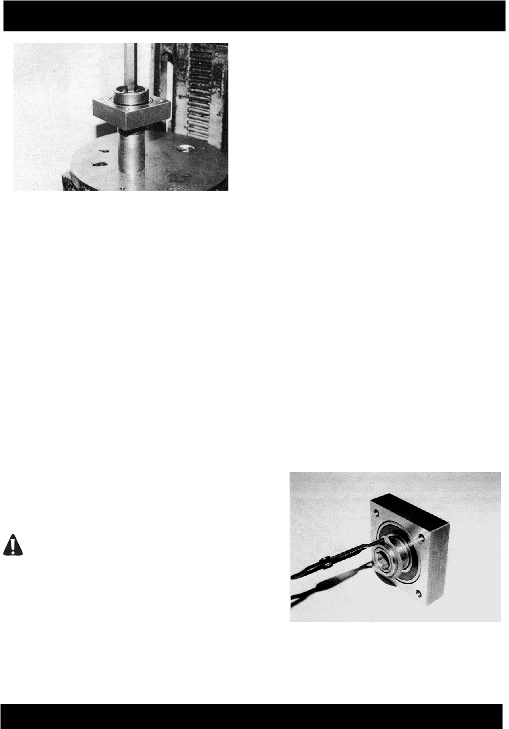
FIGURE 44
10) Mount the bearing block/driveshaft assembly to
the main frame. Tighten the 3/8 inch self-locking hex
nuts with the torque wrench to 35 ft lbs (47 Nm.)
11) Follow the instructions as outlined for
INSTALLING A REPLACEMENT-BELT OR PULLEY
to complete the assembly of the pulleys, V-belt and
belt guard.
A properly installed, replacement bearing should rotate
without excessive friction, drag and/or "rough spots".
If these symptoms occur after assembly, the bearing
was improperly supported when pressed on the
driveshaft or into the housing. The resulting thrust
placed upon the bearing exceeded its static capacity.
A bearing operating with these characteristics will
deliver minimal service life and be prone to premature
failure.
12) If the Floor Planer is powered by an engine,
reconnect the engine spark plug wire. If powered by
an electric motor and the machine is to be used
immediately, reconnect the extension cord or Surfa
ce
Grinder to the power source. Determine that the
ON/OFF switch located on the operator handle is in
the OFF position.
DANGER
UNEXPECTED MACHINE START UP CAN RESULT
IN PROPERTY DAMAGE AND/OR PERSONAL
INJURY.
INSTALLING A REPLACEMENT BEARING ON THE
OUTBOARD SIDE.
Application: All Models.
Tools Required:
1 each, 5/16 wrench.
1 each, 3/4 wrench.
1 each, 5/16 Allen wrench.
1 each, arbor press.
1 each, torque wrench, 85 ft lbs (115 Nm.) capacity,
with 5/15 inch, male Allen head and 9/16 socket.
1 each, pliers for large, external type snap rings.
Parts Required:
1 each, 29020-016 bearing.
1 each, 29020-015 snap ring (if required).
1) If the Floor Planer is powered by an engine,
disconnect the spark plug wire. If powered by an
electric motor, disconnect the extension cord or Floor
Planer from the power source.
2) Position the Floor Planer on a suitable work surface
with the V-belt approximately at waist height.
3) Using a 3/4 inch wrench, remove the access plate
capscrews. Remove the access plate.
4) Using the 5/16 inch Allen wrench and 9/16 inch
wrench, remove the be
aring block from the access
plate. For accuracy and alignment purposes, the
access plate incorporates tapped holes to properly
position the capscrews.
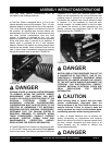
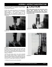
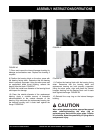
5) Position the bearing block on a suitable work
surface. A common shop vise can also be utilized.
Remove the snap ring that retains the bushing in the
bearing bore. FIGURE 45.
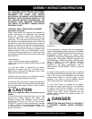
6) Position the bearing block on the arbor press with
the bearing facing up. Determine that the bearing
block is properly supported. Using the arbor press and
an appropriate sized thrust bushing, remove the
internal hexagon bushing from the bearing. FIGURE
46.
FIGURE 45