


ASSEMBLY INSTRUCTIONS/OPERATIONS
8FP FLOOR PLANER SERIES OPERATION AND PARTS MANUAL REV #2 (05/28/09) PAGE 35
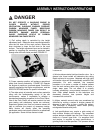
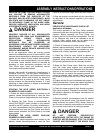
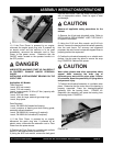
FIGURE 38.
11) If the Floor Planer is powered by an engine,
reconnect the engine spark plug wire. If powered by
an electric motor and the machine is to be used
immediately, reconnect the extension cord or Floor
Planer to the power source. Determine that the
ON/OFF switch located on the operator handle is in
the OFF position.
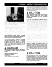
DANGER
UNEXPECTED MACHINE START UP CAN RESULT
IN PROPERTY DAMAGE AND/OR PERSONAL
INJURY.
INSTALLING A REPLACEMENT BEARING ON THE
V-BELT SIDE.
Application: All Models.
Tools Required:
1 each, 9/16 inch wrench.
1 each, 7/16 inch wrench.
1 each, torque wrench, 35 ft lbs (47 Nm.) capacity with
9/16 inch socket.
1 each, 5/16 inch Allen wrench.
1 each, pliers for large, external type snap rings.
1 each, shop press.
Parts Required:
1 each, PN 29020-016 sealed ball bearing.
1 each, container of bearing and shaft locking grade,
anaerobic adhesive/sealant.
1 each, PN 290020-011 snap ring (if required).
1 each, PN 29020-015 driveshaft (if required)
1) If the Floor Planer is powered by an engine,
disconnect the spark plug wire. If powered by an
electric motor, disconnect the extension cord or Floor
Planer from the power source.
2) Position the Floor Planer on a suitable work surface
with the V-belt approxima
tely at waist level.
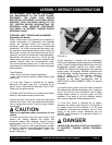
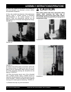
3) Using the 9/16 inch wrench, remove the belt guard
from the main frame. Clean the inside of the belt guard
with an appropriate solvent. Check for signs of wear
and damage.
CAUTION
Observe all applicable safety precautions for the
solvent.
4) Remove the V-belt and driveshaft pulley. Refer to
INSTALLING A REPLACEMENT V-BELT OR PULLEY
for specific information.
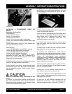
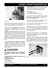
5) Using the 5/16 inch Allen wrench and 9/16 inch
wrench, remove the bearing block/driveshaft assembly
from the main frame. For accuracy and alignment
purposes, the main frame incorporates tapped holes to
properly position the capscrews.
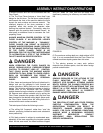
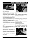
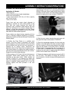
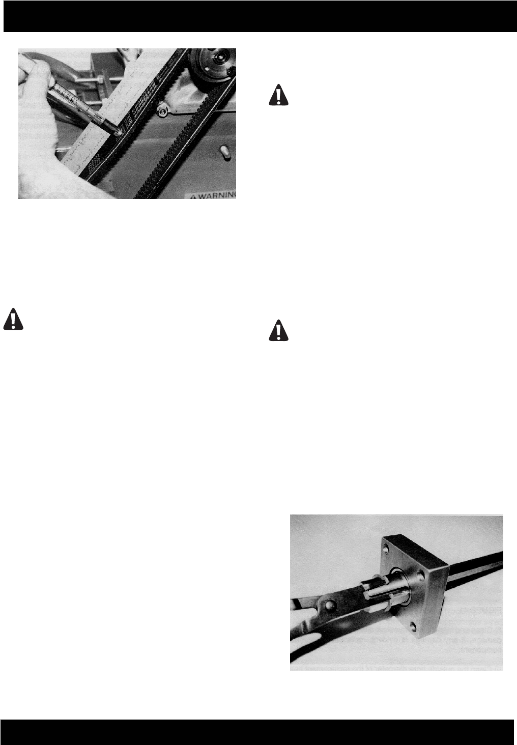
6) Position the driveshaft assembly on a suitable work
surface. Use the snap ring pliers to remove the snap
ring. FIGURE 39. Remove the spacer.
CAUTION
Wear safety glasses and other appropriate safety
apparel when removing the snap ring or
performing any work with an arbor press. Caution
all onlookers about the possibility of flying debris
and personal injury.
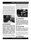
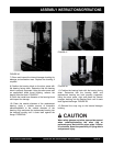
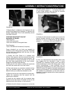
7) Position the driveshaft assembly in a suitable arbor
press. Determine that the outer race of the bearing is
properly supported. Press the bearing/driveshaft
assembly from the bearing block. FIGURE 40.
Reposition the assembly and press the bearing from
the bearing block. FIGURE 41.
FIGURE 39