


BLW-400SSW-WELDER/AC GENERATOR— PARTS & OPERATION MANUAL— REV. #1 (06/15/01) — PAGE 31
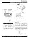
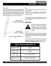
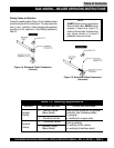
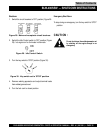
Welding Cables and Polarities
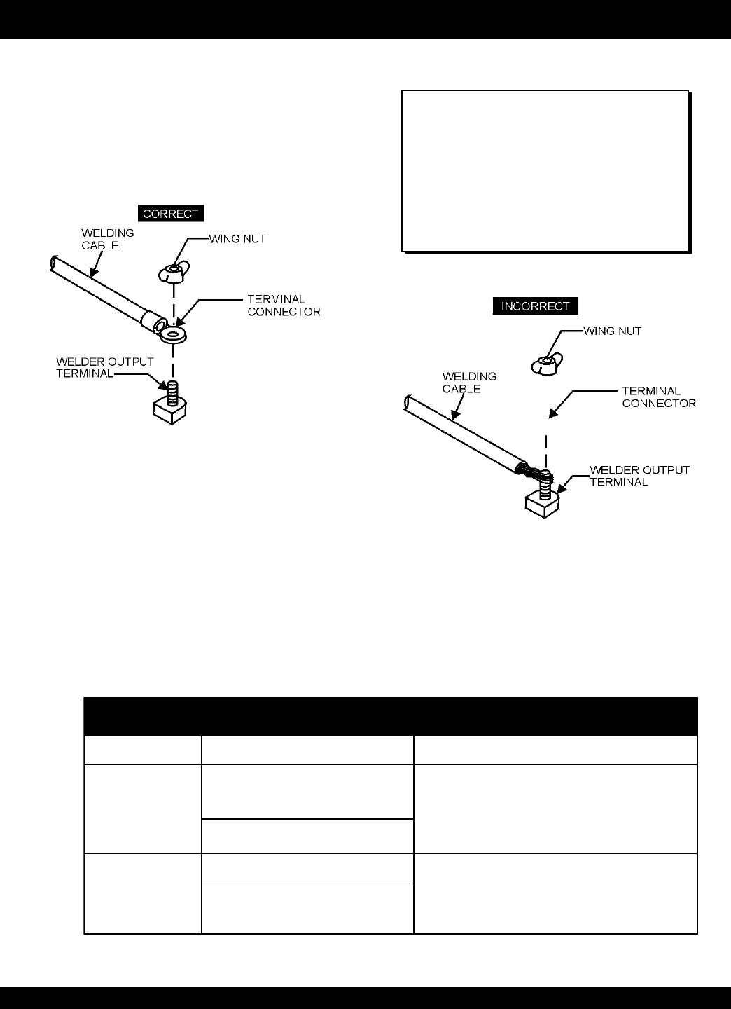
Connect the welding cables (Figure 14) to the welder's output
terminals located on the control panel. The output terminals
have (+) and (-) polarities. Select the appropriate polarities
according to the application (See Welding Applications,
Table 13).
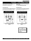
BLW-400SSW— WELDER OPERATING INSTRUCTIONS
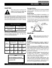
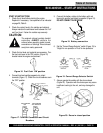
NOTE
ALWAYS attach terminal connectors at
the end of each cable. NEVER connect
exposed or frayed wires (Figure 15)
directly to the terminals. Exposed wiring
may cause shocks or di-electric
breakdown from poor contact.
Figure 14. Electrode Cable Connection
(Correct)
Figure 15. Electrode Cable Connection
(Incorrect)
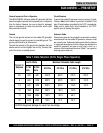
snoitacilppAgnidleW.31elbaT
YTIRALOPDOHTEMGNIDLEWSNOITACILPPALACIPYT
thgiartS
ytiraloP
)+(
...
pmalCdnuorG
)lateMesaB(
larenegrofslairetamleetsgnidleW
setalpssenkcihtdna,serutcurts
gniguogriA
yollareppocrofgnidlewcrA
redloHedortcelE...)-(
esreveR
ytiraloP
redloHedortcelE...)+(
gnidlewpu-dliuB
setalpnihtfognidlewcrA
leetssselniatsfognidlewcrA
)-(
...
pmalCdnuorG
)lateMesaB(
Table of Contents