


MQ-WHITEMAN FS2/FS2SP CONCRETE SAW — PARTS & OPERATION MANUAL — REV. #2 (06/26/06) — PAGE 23
FS2/FS2SP CONCRETE SAW — INSPECTION -BLADE PLACEMENT
■
Set the engine ON/OFF switch to the OFF
position.
■
Place the console ON/OFF button in the OFF position.
■
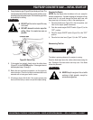
Raise the saw to a high position by cranking the Raise/Lower
handle in a counterclockwise direction.
■
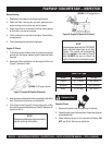
Use the Blade Nut Wrench & Blade Shaft Locking Wrench
stored on the front section of the console to install the diamond
blade.
■
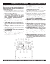
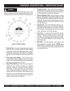
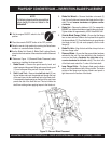
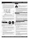
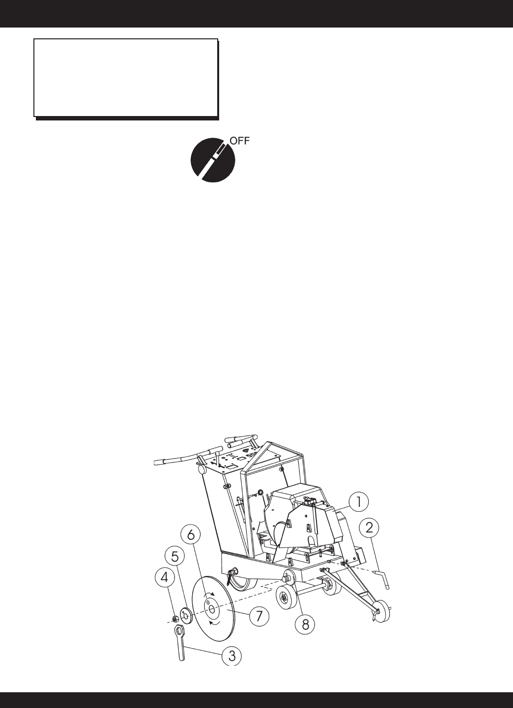
Reference Figure 13 (Diamond Blade Placement) when
removing or installing the diamond blade.
1. Blade Guard – Unscrew the guard security knob and
water hose quick disconnect fitting and remove blade guard
(1) from its bayonet fitting and set it beside the saw.
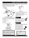
2. Shaft Lock Tool – Remove the
shaft lock tool
(2) from
the tool holder and insert the pointed end through the front
of the saw frame into the machined hole in the blade shaft.
A conveniently placed opening on the front of the saw frame
permits the use of the shaft lock tool. This tool inhibits the
shaft from rotating when applying torque to the blade nut.
NOTE
The following steps should be accomplished
before placing the diamond blade on the
blade shaft.
Figure 13. Diamond Blade Placement
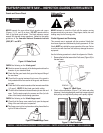
3. Blade Nut Wrench – Remove the blade nut wrench (3)
from the tool holder and unscrew the blade shaft nut (right-
side). This nut
loosens clockwise
and
tightens counter-
clockwise
.
4. Blade Nut – Remove the blade nut (4). For reassembly,
DO NOT over tighten the blade nut against the outer flange.
Tighten blade nut approximately 45-50 ft-lbs/62-69 N/m.
5. Outside Blade Flange (Collar) – Ensure that the flange
face is clean and free of debris and is placed flush against
the diamond blade (7). Check that the drive pin goes through
the blade pin hole (6) and seats properly into the inner
flange (8).
6. Blade Pin Hole – Align this hole with the drive pin hole on
the inner flange collar.
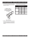
7. Diamond Blade – Ensure that the proper blade has been
selected for the job. Pay close attention to the directional
arrow on the blade,
clockwise for right-side
cutting,
counter-clockwise for left-side
cutting. The arbor hole
of the blade must match the 1" arbor of the blade shaft.
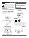
8. Inner Flange Collar – This flange is fixed upon the blade
shaft, and is manufactured with a drive pin hole. The inside
surface of the flange must be free of debris and permit a
tight closure on the surface of the blade.