


PAGE 16 — MQ-WHITEMAN FS3SP CONCRETE SAW — PARTS & OPERATION MANUAL — REV. #0 (07/15/02)
FS3SP CONCRETE SAW — CONSOLE COMPONENTS
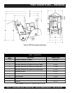
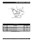
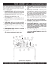
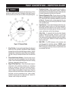
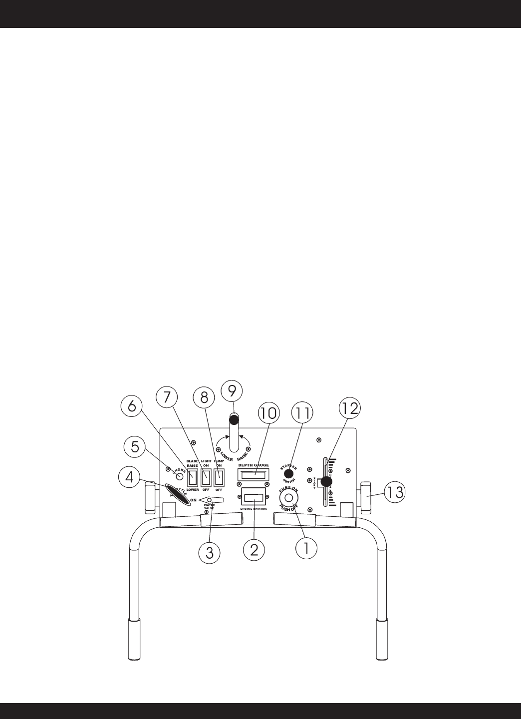
Figure 5 displays the location of the various operational control
features of the FS3SP saw. Features are dependent on the specific
model saw selected. The function of each console component or
indicator is explained below:
1. Engine ON/OFF Switch –
Pull
the switch to permit engine
starting. Push the switch to stop engine. Also acts as a fast
and secure way to stop the engine in an emergency.
2. Digital Tachometer/Hourmeter – Indicates engine RPM
and operation hours saw has been in use.
3. Water ON/OFF Valve – On position
opens
valve and
permits water to flow from source through saw water hose.
OFF position
closes
valve and halts the flow of water
through the saw.
4. Throttle Lever –
Pull
the lever to increase engine RPM.
Push
lever to decrease engine RPM (twist handle to lock).
5. Choke Lever –
Pull
lever to assist when starting a cold
engine.
Push
lever down after engine warms to disengage
choke.
6. Blade Raise/lower Switch – Raise position raises blade.
Lower position lowers blade.
7. Light Switch – On position provdes power to external
lights. Off position secures power to external lights.
8. Pump On Switch – On position provides power to external
water pump. Off position secures power to external water
pump.
9. Raise/Lower Crank Handle – IPhysically orients
saw(Raises/Lowers) depending on turn direction and
number of turns. Turning the handle "clockwise" lowers the
saw, turning the handle "counter-clockwise" raises the saw.
(Used in conjunction with the Depth Feed Gauge)
10. Depth Feed Gauge –Indicates the blade cutting depth in
inches. To activate, first lower the blade via the
crank
handle
until the blade
touches
the cutting surface. Then
roll the depth feed dial until the face label reads
zero
.
11. Start Button – A spring loaded button, that when pressed
actuates the engine start solenoid.
12. Forward/Reverse Speed Lever – Controls forward and
reverse speeds for self-propelled operation. Provides
positive neutral for engine start.
ALWAYS
place
transmission engage/disengage lever in the engage
position before setting speed lever.
13. Handle Bar Locking Knobs – Loosen or tighten these
two knobs when making adjustments to the handlebar(s).
Turn handle(s)
counter-clockwise
to loosen and
clockwise
to tighten.
Figure 5. Console Components