


PAGE 32 — MQ-WHITEMAN FS3SP CONCRETE SAW — PARTS & OPERATION MANUAL — REV. #0 (07/15/02)
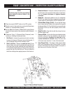
General Transmission Care
All FS3SP Models utilize spline gear wheel design coupled
with an EATON Model 7 Hydrostatic Transmission that provides
forward/reverse propulsion. The simple design of the system
keeps maintenance to a minimum.
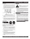
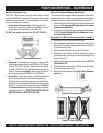
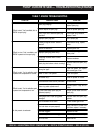
1. Transmission Reservoir Cup: Check every 8 hours
of operation. When the transmission is
cold
(A), check oil
level against the level indicator (see Figure 25).
DO NOT use multiple viscosity oils! DO NOT OVERFILL.
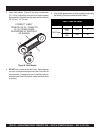
2. Servicing: The transmission reservoir is factory filled.
Should servicing be required, use SAE20W-20, API classi-
fication (SE,CC,CD) or better, General Motors Dexron B,
Ford M2C-33F, M2C-41A or International Harvester Hy-Tran
fluids. For extreme
hot weather
, drain oil and refill with an
oil having a viscosity of SAE30W-30 or SAE40W-40.
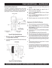
3. Drive Chain: Check every 50 hours. Periodically wipe the
chain clean and relubricate with penetrating chain oil.
The drive chain may stretch requiring tension adjustments.
Loosen the (3) transmission attachment screws (see page
68, item 11), and pivot the transmission in the
“U” slots
of
the
transmission mount
until the proper tension is achieved.
(see page 68, item 12). EXCESSIVE TENSION ON THE
DRIVE CHAIN WILL REDUCE CHAIN LIFE.
FS3SP CONCRETE SAW — MAINTENANCE
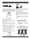
Adjust V-Belt Alignment/Replacement Pulleys
The V-belts and their respective pulleys have been professionally
aligned at the factory. If there is a requirement to remove/replace
or adjust the pulleys, proceed with the following instructions.
1. Select the proper sized pulley both in outside diameter and
arbor size. Use approved Multiquip parts to ensure the
component compatibility.
2. A change in Pulley diameters may require specifically sized
V-Belts. Contact Multiquip Servive Department to en-
sure V-Belt compatibility.
Complete Drive V-Belt(s) Replacement steps (1 through 7)
3. Remove the V-Belts from around the Pulley(s).
4. Remove the set screws that secure the pulleys to the respec-
tive shafts (PTO shaft) for engine pulley or the (bade shaft)
for the blade shaft pulley.
5. Remove/replace the pulley by sliding it off the shaft.
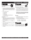
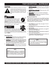
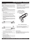
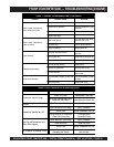
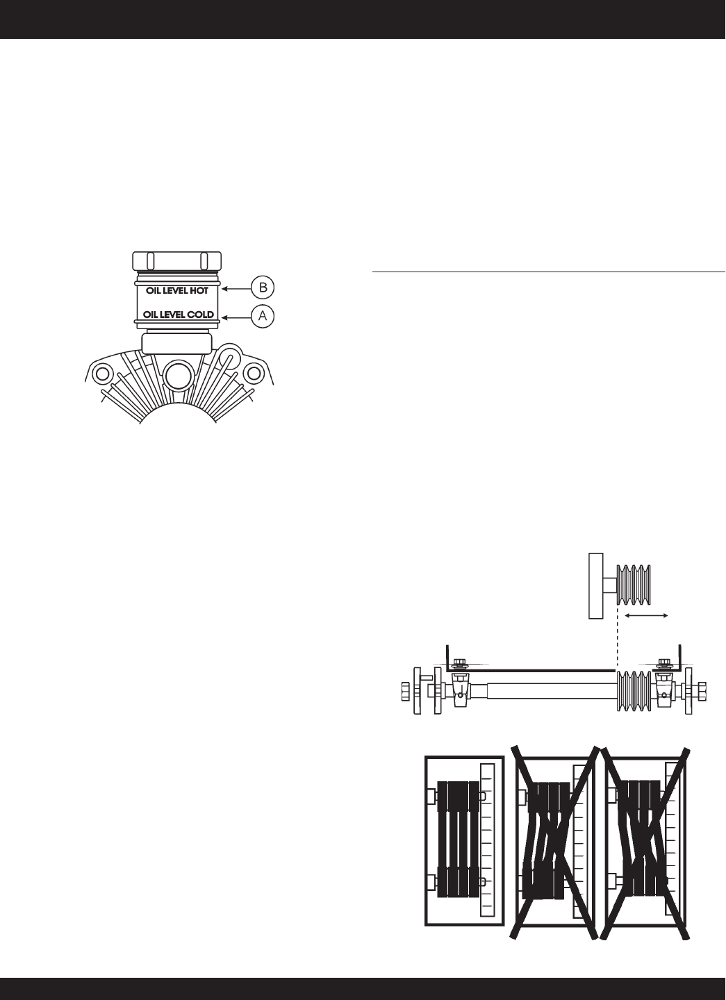
6. Reorient the new pulley on the shaft, and ensure precise
pulley alignment by utilizing an accurate straight edge (see
Figures 26 and 27).
7. Replace/tighten set screws treated with a drop of
LOCTITE
Threadlocker 266.
8. Orient the proper replacement V-Belt(s) around the blade
shaft pulley and engine pulley.
9. Reference the final stages of the Drive V-Belt(s) Replace-
ment steps.
Figure 27. V-Belt Alignment
Figure 26. Pulley Alignment
Figure 25. Transmission Reservoir