


8
60Hz: AC, Rated Frequency 60Hz
V: Voltage (V)
A: Current (A)
KVA: Power (KVA)
%: Continuous Loading Rate
IP21S: Case Protection Class. ‘IP’ is the code of International Protection. ‘2’ means preventing user’s finger
from touching dangerous parts; preventing solid material with a diameter no less than 12.5mm into the
box. ‘1’ means preventing water falling vertically, which is harmless. ‘S’ means waterproof test is
conducted while the movable parts are stationary.
4. Welder Specifications
4.1 Main Technical Data (See Table 1)
Item
MIG 175
Input Power
V
230 (220~240)
Frequency
Hz
60
Phase No.
1
Rated No-Load Voltage
V
35
Rated Input Current
A
20
Rated Input Capacity
KVA
2.3
Rated Duty Cycle
%
20
Rated Output Current/ Voltage
A/V
130/20.5
Output Current Adjustment Range
A
22~175
Cooling Type
Fan-Cooled
External Dimension: L x W x H
Inch
17.3" x 10.2" x 14.4"
Carton Dimension: L x W x H
Inch
20.5" x 12.2" x 16.1"
Weight
Lb.
49
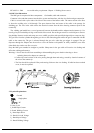
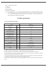
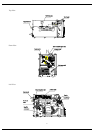
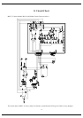
4.2 Structure of Welder
The MIG 175 portable wire feed welder case contains all the components of the welder.
The right side has the wire feed assembly, spool hub, gun trigger connections and polarity connections.
The left side houses the electrical components: transformer, reactor, current capacitor, cooling fan, controlling
transformer, PCB, heat radiator and the rectifier bridge.
The front panel contains the voltage and wire feed speed (amperage) control knobs, on/off switch, opening for the
gun connection, cooling openings, ground cable and gun trigger connections.
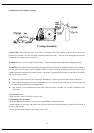
The back panel consists of the power cord, cooling opening and gas valve connection interface. (See the Chart
below)