


11
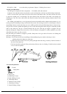
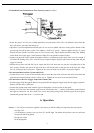
5.3 Installation and Connection for Wire Feeder System (See Chart)
* Select the proper wire for your welding application (see parameter chart). The wire diameter must match the
drive roll groove, gun liner and contact tip.
* Open drive system compartment and load spool of wire on wire spindle with wire coming off the bottom of the
spool going towards the drive system. The adaptor is used for 8" spools. Remove adaptor and put 4" spools
directly onto the spindle. Check the spool to see if it turns easily. Spool should freewheel without any binding
on the shaft. If too tight, apply a small amount of light oil to the spindle to reduce friction.
* Put the wing nut back on the spindle and tighten so there is a slight drag on the spool. If the screw is too tight, it
will affect the feeding of the wire. It needs to be just tight enough to stop the spool from turning when the gun
trigger is released.
* Release the top drive roll and flip it up to expose the drive roll. Insert the wire into the wire guide tube on the
drive system, feed the wire across the top of the drive roll into the liner on the gun side of the drive roll. Align
the wire with proper drive roll groove. Tighten the set screw on the drive roll when it is properly aligned.
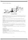
5.4 Connection Between Drive System and Torch
* Loosen the set screw on top of the connection block, insert the end of the torch into the torch access hole and
push into the connection block until it is all the way in. Tighten the set screw on the connection block.
5.5 Connection of the Gun Trigger Leads and Ground Cable
* Feed the trigger leads through the hole for the ground cable and plug the trigger leads into the trigger receptacle.
Polarity does not make a difference.
* Connect the ground clamp cable with the lug on it through the wire access hole on the panel.
* Polarity: For solid wires the electrode (gun) must be connected to the “+” polarity stud and the ground lead on
the negative connection. For flux cored wires reverse the polarity and put the electrode (gun) on the negative
stud and the ground cable on the “+” positive stud.
6. Operation
Notice: * Turn off power and close regulator valve when you finish welding or temporarily leave the jobsite.
* Always wear:
1) A full helmet to protect your eyes from UV and IR light. The helmet also protects your face and neck
from sparks and flying debris.
2) Long sleeve shirt
3) Full length pants