


7
IEC 60974-1: 2000 Arc welder safety requirement. Chapter 1: Welding Power source
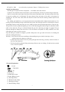
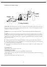
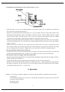
3.4 MIG Gun Illustration
The MIG gun is composed of three components: Gun handle, cable and connector.
Connector is the end that connects into the drive system and interfaces with the wire feeder and gas connection.
Cable is covered with a nylon tube with a liner in the center of the hollow cable. The center section of the liner
is where the welding wire is fed through. The space between liner and center of the cable is the passage for
shielding gas. The wire in the cable carries the electrical current from the drive housing connector point to the
contact tip.
The welding gun handle has a curved gooseneck between the handle and the adaptor/nozzle/contact tip. Use
nozzle gel to prevent buildup of slag on the inside of the nozzle. Do not hit gun nozzle on a solid object to remove
slag buildup. Remove nozzle and scrape out or use a MIG gun pliers with specially designed tip to scrape out slag.
The gas flows from the cylinder through the gas valve to the connecting point where the gun is connected with the
cable to the contact tip. The gas is released through the gas valve when the gun trigger is engaged. The gas
disperses through the adaptor into the nozzle to cover the molten weld puddle. In windy conditions, user must
either block the wind or use flux core wire.
Keep the MIG gun extended as straight as possible. Sharp turns in the gun cable will restrict wire feeding and
affect the welding performance.
Warning: * Power must be off when assembling or disassembling the gun to the drive housing or when
replacing the nozzle, adaptor or contact tip.
* Contact tips wear because of the wire passing through them and arcing, caused by electrical contact of
the wire to the contact tip.
* The liner should be replaced if dirty and causing friction to the wire feeding. If cable has been crushed
or cut, it must be replaced.
3.5 Symbol Explanations
Ground
Single phase
DC
X: Duty Cycle
I
1
: Rated Input Current
I
2
: Rated Welding Current
P
1
: Rated Input Power
U
0
: Rated No-Load Voltage
U
1
: Rated Input Voltage
U
2
: Rated Welding Voltage