


2
Northern Industrial Welder
O
p
eratin
g
Instructions and Parts Manual
Flux Core 125
Wire Feed, Gasless Welder
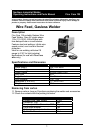
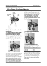
1.3 After unpacking unit, inspect for any damage that may have occurred during
transit. Check for loose, missing, or damaged parts. Shipping damage claim
must be filed with carrier.
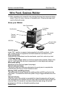
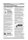
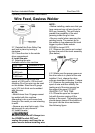
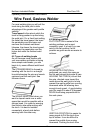
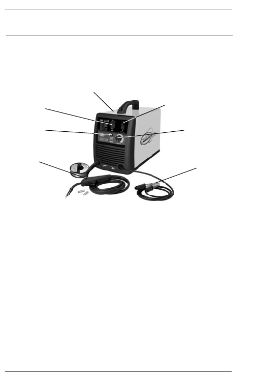
Know your Welder
ON/OFF Switch
In the “OFF” position no power is being supplied to the MIG gun/torch. In the
“ON” position power is supplied to the main transformer and control circuit
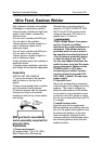
Wire compartment
Inside the wire compartment are the wire feeder, spool hub, and set up chart.
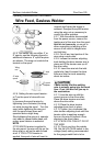
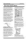
1-2 Voltage Setting
1 (low), 2 (high) voltage switch is on the front panel of the machine, Refer to the
“set up” chart inside the wire feed compartment for initial adjustment settings.
Wire speed setting
Adjustment of the wire feed speed (amperage).
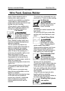
Ground cable and clamp
The ground cable and clamp are attached to the work piece to complete the
circuit allowing the flow of current needed to weld.
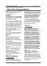
Welding Cable and MIG gun/torch
The welding wire is driven through the welding cable and MIG gun/torch to the
work piece. It is attached to the drive system, the gun trigger activates the drive
motor.
Thermal Indicator
If the duty cycle of the welder is exceeded the internal temperature will exceed
safe temperatures the machine will shut down and the thermal overload light will
come on.Allow 15 minutes for cool down before the light will go off and the
temperature to fall into an allowable operating range.
Power Cord
On/off switch
1-2 voltage
Setting
Wire speed
setting
Ground cable
and clamp
MIG Gun
Thermal
Overload
indicator
Wire Compartment