


7
Northern Industrial Welder
O
p
eratin
g
Instructions and Parts Manual
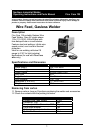
Flux Core 125
Wire Feed, Gasless Welder
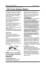
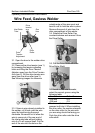
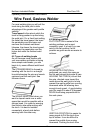
3.1. Open the door to the welder drive
compartment.
3.2. Remove the drive tension (see 1)
by loosening the tension adjusting
knob and lifting the Drive Tension
Adjustor away from the Drive Tension
Arm (see 2). Lift the drive tension arm
away from the drive roller (see 3).
See following images for reference
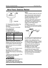
3.3. If there is wire already installed in
the welder, roll it back onto the wire
spool by hand-turning the spool
clockwise. Be careful not to allow the
wire to come out of the rear end of
the inlet guide tube without holding
onto it or it will unspool itself. Put the
end of the wire into the hole on the
outside edge of the wire spool and
bend it over to hold the wire in place.
Remove the spool of wire from the
drive compartment of the welder.
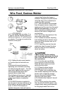
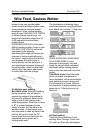
3.4. Rotate the Drive Roller Cap
counterclockwise and remove it from
the Drive Roller.
3.5. Pull the Drive Roller off of the
Drive Roller Shaft.
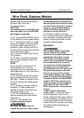
3.6 Based on the wire diameter,
select the correct groove using the
following table.
Wire Diameter Roller Groove
.030 inch 0.9
.035 inch 0.9
The drive roller has two wire size
grooves built into it. When installing
the drive roller, the number stamped
on the drive roller for the wire size
you are using should be facing you.
Push the drive roller onto the drive
roller shaft.
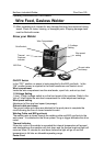
Drive
tension
arm
Inlet Guide
Tube
Gun
liner
Drive
Roller
Drive
Tension
Adjustment