


-)
INNER SHIELD
To Analyzer:
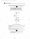
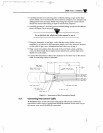
Refer to the instrument instruction manual and connect the
interconnect cable wires to appropriate SENSOR terminals in the same way as
the sensor wires would be directly connected.
9
(TEMP
StuE
+)
SHIELD
RED (DRIVE)
BLACK
(
SENSE
)
WHITE
(
TEMP
L6.41
SENSOR
Typ
_
0.25
FOIL
Figure 2-5. Interconnect Cable Termination Details
Connecting Interconnect Cable
SHIELO
[mm]
INNER
OlMS
INCH
-
CELLOPHANE BINDER
ALL
FOlL
SHlELO
_I
,
cable, by matching colors as indicated.
OUTER CABLE JACKET
BARE INNER SHIELD WIRE
OUTER
%
inch of insulation from the ends of the red, black, white, and blue
wires. Tin these leads, the insulated sensor shield wire, and the bare inner
shield wire with solder.
9. Connect the interconnect cable to the analvzer in the same wav as the sensor
”
Do not fold back the cellophane
binder exposed in step 4.
3.3
7. Using an ohmmeter or test light, verify that the sensor shield wire you
insulated is not shorted to the bare inner shield wire. If the wires are shorted,
cut the cable to get a new unfinished end and start over at step 1.
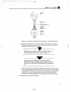
8. Strip
2%
inch long piece of shrink tubing or tape on the bare
sensor shield wire %-inch from the end as shown in Figure 2-6 to insulate and
distinguish it from the inner shield wire. Doing this exposes X-inch of bare
shield wire beyond the tubing or tape for connection purposes.
6. Carefully position a l-inch long piece of shrink tubing or tape on the cable as
shown in Figure 2-6 to secure all wires.
-
Installation
5.
Carefully position a
m
CDE68 1 Part 2
2:14
PM Page 9
7/17/03
M3594m0603mCDE681Series.qxd