


2005 OutBack Power Systems Inc.
l
28
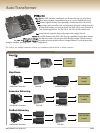
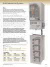
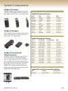
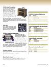
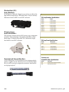
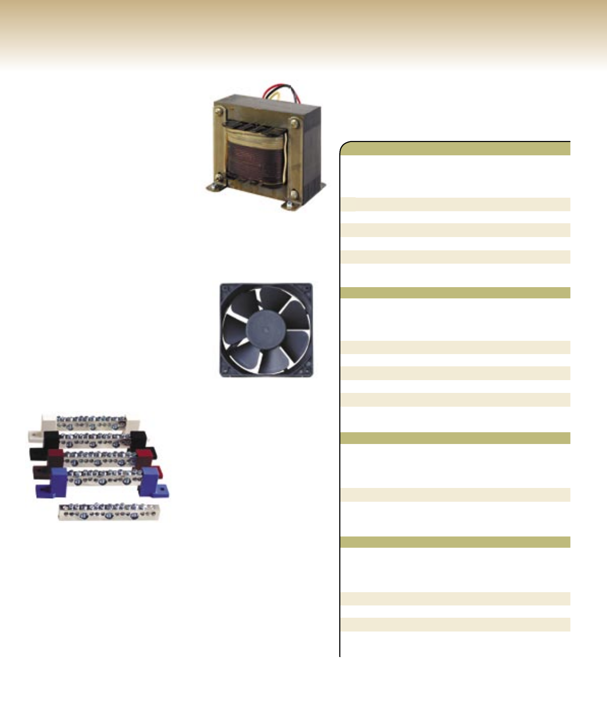
X-240 Auto Transformer
e same auto transformer and
breakers as the PSX-240 but
designed to be housed within the
PS2AC or PS4AC. It can be used
for step-up, step-down, generator
and split phase output balancing
or as a series stacked inverter-to-
load balancing auto-former. It can
also transfer up to 2kW (3kW with
the optional X fan kit) from one side of the total
power rating of the generator or the total power rating of an
OutBack stacked series/parallel 120/240 VAC inverter/charger
confi guration.
X-Fan Kit
e X-Fan Kit increases the power
rating of the X-240 to a maximum
of 6 kVA continuous. ermostatic
controlled 120 VAC powered.
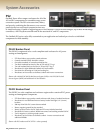
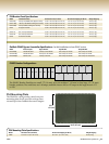
Terminal and Ground Bus Bars
Use for adding more wire
terminations or for isolating
multiple positive / negative cir-
cuits. All TBB and GBB models
have three #1/0 to 14 AWG and
eight #6 to 14 AWG screw type
compression terminals, which
means no ring lugs required.
Available with black, white and
red insulators. e Battery Bus is .25" (7 mm) thick tin plated
copper and can be mounted on the back plate of the PS2DC /
PS4DC or directly on the battery breaker terminals.
Conduit Adapters
Allows connection of the FX and VFX inverter/chargers to the
PS2 and PS4 breaker panels or 2" conduit.
Mounting Brackets
e mounting bracket allows MX60 charge controllers to be
mounted on the side of the PS2DC or PS4DC enclosures.
19
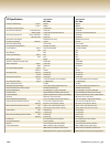
Terminal and Ground Bus Bars Specifi cations
Model Description
GBB Ground Bus Bar not insulated
TBB Terminal Bus Bar with black insulators
TBB-B Terminal Bus Bar with blue insulators
TBB-R Terminal Bus Bar with red insulators
TBB-W Terminal Bus Bar with white insulators
Mounting Brackets Specifi cations
Model Description
PS2-CCB One MX60
PS2-CCB2 Two MX60s
PS4-CCB2 Two MX60s
X-240 Auto Transformer Specifi cations
Model Description
X-240 120/240 VAC 60 Hz
2.0 kW without Fan Kit
3.0 kW with X-Fan Kit
X-Fan Kit Thermostatic controlled brushless fan 120 VAC Powered
Conduit Adapters Specifi cations
Model Description
ACA FX and VFX AC end
DCA FX and VFX DC end