


24
Warning
WarningWarning
Warning
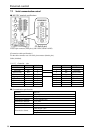
7 External control
7.1 External input/output control
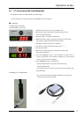
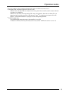
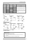
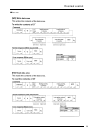
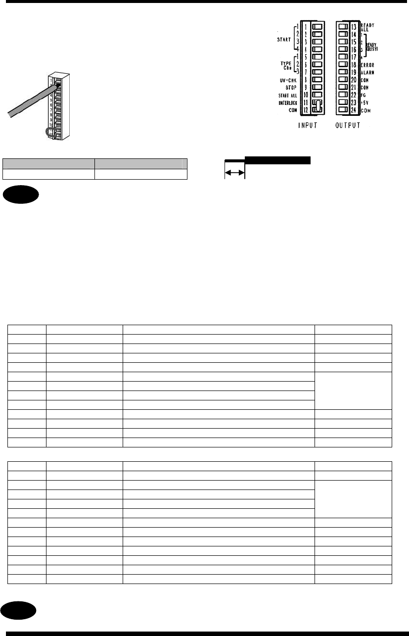
■External control connectors (12 pin × 2)
MINI COMBICON Plug 12P
(PHOENIX CONTACT: MC 1.5/12-ST-3.5)
(Osada: OS-85-12P)
Compatible wiring (stranded)
Tightening torque: 0.22 to 0.25 Nm
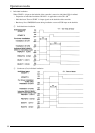
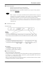
Precautions for wiring
・ Carefully strip the cover so as not to damage the core wires.
・ Connect the core wires without twisting them.
・ Connect the core wires without soldering them; otherwise, they may break due to vibration.
・ After connection, do not apply stress to the cable.
・ Because of the terminal structure, if the wire is tightened by a counterclockwise rotation, the
connection will fail. In such cases, pull out the wire, check the terminal hole, and then connect it
again.
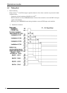
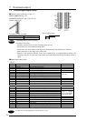
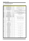
■Input/output terminal table
INPUT
Pin No Signal name Description
1 START 1 CH1 irradiation start signal
2 START 2 CH2 irradiation start signal
3 START 3 CH3 irradiation start signal
4 START 4 CH4 irradiation start signal
5 TYPE Chg1 Product type switching signal
6 TYPE Chg2 Product type switching signal
7 TYPE Chg3 Product type switching signal
8 UV CHECK UV intensity control mode signal
UJ35 only
9 STOP Irradiation stop signal, Error reset
10 START ALL CH1-CH4 irradiation start signal
11 INTERLOCK Interlock (normally ON)
12 COM Common terminal for input/output signals
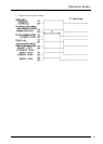
OUTPUT
Pin No Signal name Description
13 READY ALL ON when irradiation is ready to start
14 READY1/BUSY1 ON when CH1 irradiation is ready to start/in progress
15 READY2/BUSY2 ON when CH2 irradiation is ready to start/in progress
16 READY3/BUSY3 ON when CH3 irradiation is ready to start/in progress
17 READY4/BUSY4 ON when CH4 irradiation is ready to start/in progress
READY/BUSY
singal is changed
over by changing the
initial setting mode.
18 ERROR Error signal
19 ALARM Warning signal (temperature/time warning)
20 COM Common terminal for input/output signals
21 COM Common terminal for input/output signals
22 FG Frame gland
23 +5V 5 V DC output (for display or output signals)
24 COM Common terminal for input/output signals
* Pin Nos. 12, 20, 21 and 24 are connected internally.
The ON time of input signal pulses must be 100 ms or more.
Size Conductor section area
AWG#24-16 0.2 - 1.25 mm
2
6-7 mm
Wire stripping length
Warning
WarningWarning
Warning