


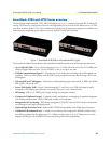
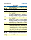
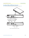

SmartNode 4980 and 4990 Series rear panels 19
SmartNode 4980 & 4990 User Manual 1 • General information
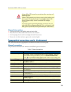
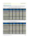
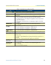
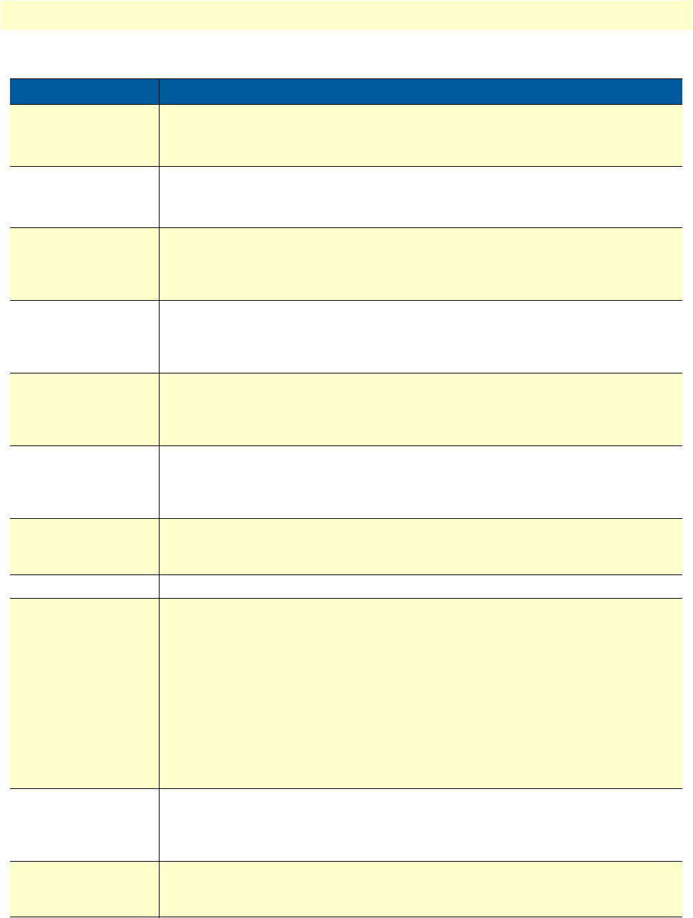
Table 6. Rear panel ports
Port Description
WAN ETH 0/0-0/1
(SN4991
models only)
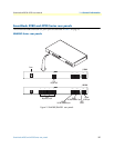
Auto-MDX Gigabit-Ethernet port, RJ-45 (see
figure 2
), connects the unit to an Ethernet
WAN device (for example, a cable modem, DSL modem, or fiber modem). Note:
Only full duplex modes are supported.
LAN ETH 0/1-0/1
(SN4980/4981
models only)
Auto-MDX Gigabit-Ethernet port, RJ-45 (see
figure 2
), connect the unit to an Ethernet
LAN (for example, a PC, printer, or wireless bridge). Note: Only full duplex modes
are supported.
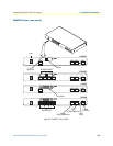
PRI 0/0 RJ-45 connector providing E1 (2.048Mbps) or T1(1.533 Mbps) PRI interface, meet-
ing all requirements of ITU-T recommendations for G.703. Use a shielded E1 or T1
interface cable for 120 Ohm balanced connections to connect the SmartNode with
an NT or ET, e.g. a PBX or LE.
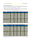
PRI 0/1 RJ-45 connector providing E1 (2.048Mbps) or T1(1.533 Mbps) PRI interface, meet-
ing all requirements of ITU-T recommendations for G.703. Use a shielded E1 or T1
interface cable for 120 Ohm balanced connections to connect the SmartNode with
an NT or ET, e.g. a PBX or LE.
PRI 0/2 RJ-45 connector providing E1 (2.048Mbps) or T1(1.533 Mbps) PRI interface, meet-
ing all requirements of ITU-T recommendations for G.703. Use a shielded E1 or T1
interface cable for 120 Ohm balanced connections to connect the SmartNode with
an NT or ET, e.g. a PBX or LE.
PRI 0/3 RJ-45 connector providing E1 (2.048Mbps) or T1(1.533 Mbps) PRI interface, meet-
ing all requirements of ITU-T recommendations for G.703. Use a shielded E1 or T1
interface cable for 120 Ohm balanced connections to connect the SmartNode with
an NT or ET, e.g. a PBX or LE.
Console
Used for service and maintenance, the Console port (see
figure 2
), an RS-232 RJ-45
connector, connects the product to a serial terminal such as a PC or ASCII terminal
(also called a dumb terminal).
DC power input
Electricity supply socket. (see
figure 2
).
Reset
The reset button (see
figure 2
) has three functions:
•
Restart the unit with the current startup configuration—Press (for less than 1 second)
and release the Reset button to restart the unit with the current startup configuration.
•
Restart the unit with factory default configuration—Press the Reset button for
5 seconds until the Power LED (see
figure 4
on page 20) starts blinking to restart
the unit with factory default configuration.
•
Restart the unit in bootloader mode (to be used only by trained SmartNode tech-
nicians)—Starting with the unit powered off, press and hold the Reset button as
you apply power to the unit. Release the Reset button when the Power LED starts
blinking so the unit will enter bootloader mode.
G.SHDSL port
(SN4991 /2GS
models only)
Provides symmetrical throughput up to 11.4 Mbps over four wires or 5.7 Mbps over
two wires. Supports ATM QoS with multiple PVCs and outstanding DSLAM interop-
erability. The G.SHDSL LEDs are located on either side of the DSL port. ACT (when lit
or blinking) shows Activity, and LINK (when lit) shows that the DSL port is connected.
X.21 serial port
(SN4991 /D
models only)
DB-15 connector providing data rates up to 2 Mbps, Frame Relay or PPP protocols,
Status and Activity LED indicators, configured as DTE.