


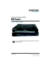

OnSite 3300 Quick Start Guide 5
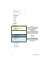
2.0 Connecting Interfaces
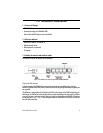
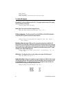
2.1 Connecting Console Interface
Install the supplied RJ-45-to-RJ-45 cable with the DB9-RJ45 adapter between the OS3300 RS-232 port and an
open serial port on your computer. If you need to assemble your own cable, refer to the pinout diagram in
figure 5.
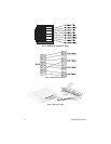
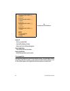
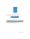
Figure 5. DB-9-to-RJ-45 cable diagram
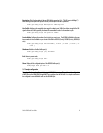
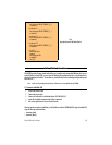
2.2 Connect the Ethernet Interface
The EFM Router has four unshielded RJ-45 auto-MDIX10/100Base-T interfaces. These are designed to connect
directly to a 10/100Base-TX network. Figure 6 shows the signal/pin relationships on this interface. You may
connect this port to a hub or PC using a straight through or crossover cable that is up to 328 ft long.
2.3 Connect the PoE Interface (optional)
The RJ-45 port is an Auto-MDIX 10/100Base-T interface. This port is designed to connect directly to a 10/
100Base-T network. Figure 6 shows the signal/pin relationships on this interface. You may connect this port to
any Ethernet enabled device using a straight-through or crossover cable that is up to 328 ft long. PoE enabled
devices such as IP cameras, Voice over IP (VoIP) phones and wireless access points may draw the PoE. The router
injects power on the data pair pins 1/2 (PoE+) and 3/6 (PoE-) of the connector labeled “Eth 3.” The power injec-
tion conforms to the 802.3af specification, and will deliver the 55 volts with a maximum of 13 watts. A 12 volt 3
amp external power supply is required for PoE.
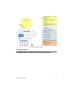
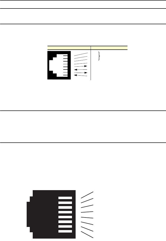
Figure 6. OS330010/100Base-T RJ-45 Connector Pinout
6 DSR
1 CD
4 DTR
5 SG
2 RD (driven by access server)
3 TD (received by access server)
8 CTS (driven by access server)
7 RTS (received by access server)
1
2
3
4
5
6
7
8
Wired together
(No otherelectrical
connection)
RJ-45 Jack Signal NameDB-9
1 TX+ (data output, PoE+)
2 TX- (data output, PoE-)
3 RX+ (data input, PoE+)
4 (no connection)
5 (no connection)
6 RX- (data input, PoE-)
7 (no connection)
8 (no connection)
1
2
3
4
5
6
7
8