


OEM Catalogue 2009/2010 3.113
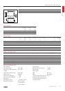
HID Gear
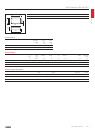
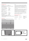
D1
A2
B1
B2
A3
A1
C1
HID-DV
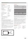
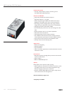
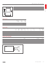
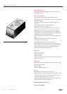
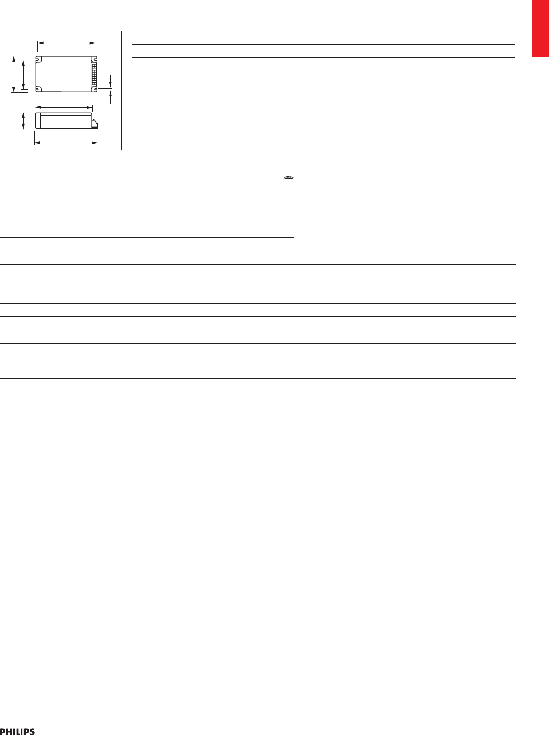
Type A1Nom A2Nom A3Nom B1Nom B2Nom C1Nom D1Nom
HID-DynaVision DALI 150.0 134.0 136.0 90.0 70.0 40.0 4.5
HID-DynaVision DALI SON and CDO
Inrush current
Type Maximum
gear number
on MCB
(x)
Inrush
current
Peak
(A)
Inrush
current
Width
(ms)
HID-D DALI 100-150 /S CDO/SON/SDW 6 50 0.45
Electrical data
Type Number
of
Lamps
(x)
Rated
Gear-
Lamp
Power
Line
Frequency
(Hz)
Line
Voltage
(V)
T-case
life
(ºC)
T-case
maximum
(ºC)
T-ambient Ignition
Voltage
(kV)
Cable-Cap
outputwires
mutual
(pF)
HID-D DALI 100-150 /S CDO/SON/SDW 1 100-150 50/60 220-240 90 100 45 4.00 1000
Ordering and packing data
Type EAN code
1 piece
Weight Qty bulk
packing
Dimensions bulk packing EAN code
bulk packing
EOC
8711500
HID-D DALI 100-150 /S CDO/SON/SDW 8711500928733 0.725 kg 10 39.8 cm x 16 cm x 11.1 cm 8711500928740 928733 30
Electrical installation notes
Mains operation
Rated mains voltage 220-240 V
With tolerances for performance
+6%-8%
203-254 V
With tolerances for operation 180-264 V
Mains frequency 50/60 Hz
Power factor 100% power >0.98
Power factor 35% power >0.93
Earth leakage current <0.2 mA per driver
Overvoltage protection 48 hrs at 325 Vac
2 hrs at 366 Vac
5 min. at 400 Vac
Lamp operation
Operation frequency (typical) 125 Hz
Ignition voltage 3-4 kV
Cable capacity
SON-100-150W lamps (2.7 kV) Max. 1 nF
CDO-lamps (3.3 kV) Max. 0.5 nF
Air and creepage distance from any
(metal) part that may become live,
to earthed environment (class I) or
test finger (class II)
>4 mm
Notes:
1. With three-phase mains supply, neutral should never be
disconnected; otherwise circuitry could be damaged.
2. For proper EMC, wiring inside luminaire should be as straight and as
short as possible; mains wires should not run parallel to lamp wires.
3. Driver should be mounted in luminaire >min IP 23.
4. Thermo-protected circuit incorporates self-resetting facility; ignition
attempts stop after seven minutes; mains supply must be switched off
and on to reset driver.
5. Insulation resistance test: 500 Vdc from Line/Neutral to Earth (not
between Line and Neutral). Ensure that the Neutral is reconnected
again after abovementioned test is carried out and before the
installation is put into operation.