


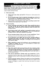
10
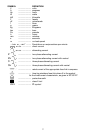
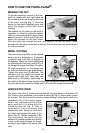
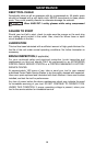
2. The cutter adjusting lever (C) Fig. 4 is located to the left of the handle directly
behind the motor housing. Turn this lever to the position shown in Fig. 4.
3. Place a straight edge across the cutter opening (Fig. 5), so that it rests on
both the front and rear shoe. Turn the cutter by hand until it lifts the straight
edge to its maximum height. Adjust the lever (C) Fig. 4 until the top of the
cutting edge just touches the straight edge while it rests evenly on both
shoes. The cutter is set for “zero” cut.
4. Make this adjustment each time a new or re-sharpened cutter is installed in
the plane.
ADJUSTING THE CUTTER
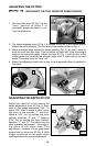
DISCONNECT THE TOOL FROM THE POWER SOURCE!
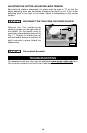
1. Set the cutter lever (B) Fig. 3 to the
“zero” position to allow it to
accurately gauge the depth of cut.
Turn the plane over.
B
C
Fig. 3
Fig. 5
Fig. 4
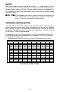
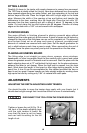
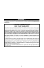
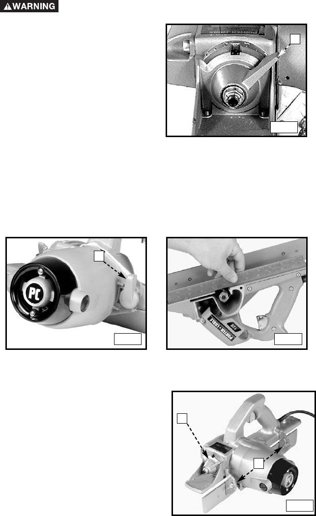
ADJUSTING FOR DEPTH OF CUT
Adjust your depth of cut by moving the
depth adjustment lever (D) Fig. 6. Each
mark on the gauge represents 1/64". To
plane 1/32" from a board or door, move
the lever to the number “1” position.
Make a 1/64" cut by setting the lever
halfway between “0” and “1”. Make a
3/64" cut by setting the lever halfway
between “1” and “2”. The plane has one
other operating adjustment - the angle of
the apron to the plane shoe. This
adjustment consists of two graduated
hinges held by wing nuts (E) Fig. 6. Both
hinges should be on the same angle
markings before the nuts are tightened.
D
E
Fig. 6