


HOW TO USE THE PORTA-PLANE
®
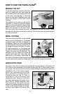
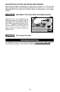
MAKING THE CUT
To provide maximum control of the tool,
hold the planer with the right hand on
the handle and the left hand on the front
of the motor housing (Fig. 7). Rest the
thumb on the depth adjusting lever and
wrap the fingers around the motor
housing.
The position of the plane on the work is
important in obtaining optimum results.
Hold the plane shoe and the apron firmly
against the work. At the start of the cut,
place the pressure on the front shoe.
After the plane has entered the work, put pressure on the rear shoe. Follow
through with the plane to the end of the cut and continue the rear pressure until
the cut is complete.
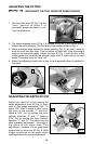
BEVEL CUTTING
The plane may be quickly set for outside
bevel cuts from 0 degrees to 15 degrees
or inside bevel cuts from 0 degrees to
45 degrees. Make the bevel adjustment
by loosening the two wing nuts (A) Fig. 8
on the apron hinges and tilting the apron
(B) until the pointers on the hinges line
up with the desired angle graduations.
Tighten the wing nuts (A) securely. The
beveled cuts are made the same as
regular right-angle cuts. More than one
pass may be necessary, depending on
the width of the bevel. Keep the plane shoe and the apron pressed firmly against
the work during the entire cut. Make each cut for the full length of the board.
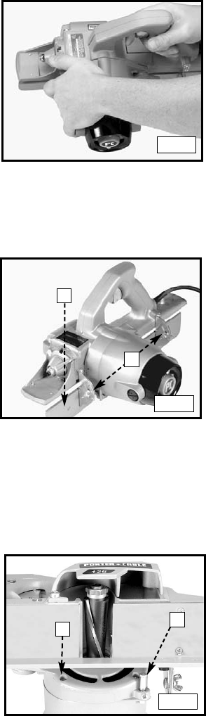
APRON STOP STUD
The apron stop stud is located directly behind the front hinge of the apron (A)
Fig. 9 and on the underside of the motor housing (B) Fig. 9, and is held in place
by a screw. This stud is used to produce exact settings of the apron quickly for
repeated cuts of the same angle.
Select the required setting of the
apron and lock it in place with the
thumb screws (A) Fig. 8. With a
screwdriver, turn the screw and
release the stud. Move the stud until
the head rests against the side of the
apron (Fig. 9). Tighten the screw. After
this procedure, the apron can be
adjusted to smaller angles and quickly
re-set to the original angle by simply
moving it back against the apron stop
stud.
11
Fig. 7
B
A
Fig. 8
B
A
Fig. 9