


7
MOTOR
Many Porter-Cable tools will operate on either D.C., or
single phase 25 to 60 cycle A.C. current and voltage
within plus or minus 5 percent of that shown on the
specification plate on the tool. Several models, however,
are designed for A.C. current only. Refer to the
specification plate on your tool for proper voltage and
current rating.
CAUTION: Do not operate your tool on a current
for which the voltage is not within correct limits.
Do not operate tools rated A.C. only on D.C.
current. To do so may seriously damage the tool.
EXTENSION CORD
SELECTION
When servicing use only identical replacement parts.
To reduce the risk of electric shock, this equipment has a
polarized plug (one blade is wider than the other). This
plug will fit in a polarized outlet only one way. If the plug
does not fit fully in the outlet, reverse the plug. If it still
does not fit, contact a qualified electrician to install the
proper outlet. Do not change the plug in any way.
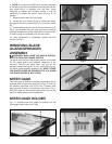
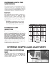
Make sure your extension cord is in good condition and
be sure to use one heavy enough to carry the current of
the saw. An undersized cord will cause a drop in line
voltage resulting in loss of power and overheating. Fig.
15B, shows the correct size to use depending on cord
length. If in doubt, use the next heavier gage. The smaller
the gage number, the heavier the cord.
0-6
0-6
0-6
0-6
120
120
120
120
up to 25
25-50
50-100
100-150
18 AWG
16 AWG
16 AWG
14 AWG
Ampere
Rating
Volts
Total Length of
Cord in Feet
Gage of
Extension Cord
6-10
6-10
6-10
6-10
120
120
120
120
up to 25
25-50
50-100
100-150
18 AWG
16 AWG
14 AWG
12 AWG
10-12
10-12
10-12
10-12
120
120
120
120
up to 25
25-50
50-100
100-150
16 AWG
16 AWG
14 AWG
12 AWG
12-16
12-16
12-16
120
120
120
up to 25
25-50
14 AWG
12 AWG
GREATER THAN 50’ NOT RECOMMENDED
MINIMUM GAUGE EXTENSION CORD
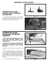
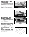
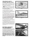
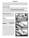
FASTENING SAW TO TWO
SAW HORSES
When fastening the saw to two saw horses, position the
four grooves located on the base of the saw cabinet
over the 2x4’s of the saw horse and fasten in place with
suitable hardware (not supplied). CAUTION: THE SAW
HORSES MUST BE ABLE TO SUPPORT 300 LBS.
Fig. 15B
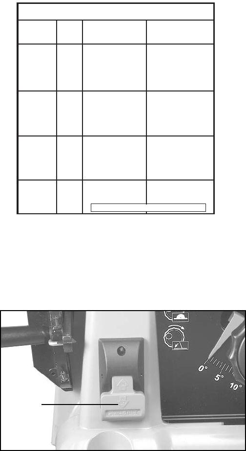
OPERATING CONTROLS AND ADJUSTMENTS
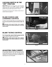
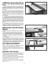
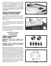
STARTING AND STOPPING
SAW
The “ON/OFF” switch (A) Fig 16, is located on the front
of the saw cabinet. To turn the saw “ON” pull the
“ON/OFF” switch (A) out. To turn the saw “OFF”, push
in on the “ON/OFF” switch (A).
Fig. 16
A