8
BLADE RAISING AND
LOWERING CONTROL
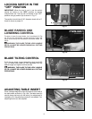
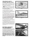
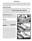
To raise or lower the saw blade, turn handwheel (A) Fig
18. Turning the handwheel counterclockwise lowers the
blade and turning the handwheel clockwise raises the
blade.
WARNING: THE BLADE TILTING LOCK HANDLE
(B) FIG. 19, MUST BE LOCKED DURING ALL CUTTING
OPERATIONS.
Fig. 18
BLADE TILTING CONTROL
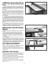
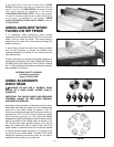
To tilt the saw blade, loosen blade tilting lock handle (B)
Fig. 19, rotate outer wheel (C) until the blade is at the
desired angle and tighten lock handle (B).
WARNING: THE BLADE TILTING LOCK HANDLE
(B) FIG. 19 MUST BE LOCKED DURING ALL CUTTING
OPERATIONS.
Fig. 19
A
B
C
LOCKING SWITCH IN THE
“OFF” POSITION
IMPORTANT: When the tool is not in use the switch
should be locked in the “OFF” position to prevent
unauthorized use. The tool can be locked in the “OFF”
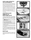
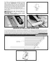
position using a padlock (A) as shown in Fig. 17.
The padlock should have 3/16" diameter shank with a 2"
throat to insure a proper fit.
Fig. 17
A
ADJUSTING TABLE INSERT
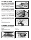
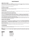
Place a straight edge (B) across the table at both ends of
the table insert as shown in Fig. 19A. The table insert (A)
should always be level with the table. If an adjustment is
necessary, turn the adjusting screws (C), as needed. Four
adjusting screws (C) are supplied.
B
A
C
C
Fig. 19A


