


10
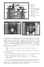
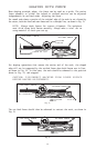
PLUNGE ROUTER MODEL 7538 OR 7539
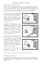
1. Move the plunge locking lever (on the router), to the released position.
2. Rotate Model 75300 Height Adjustment Knob to raise or lower cutter to
the desired position.
3. Release plunge locking lever and push lever to the locked position.
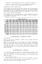
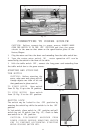
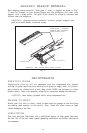
ADJUSTING THE FENCE
Each fence may be adjusted individually for front-to-back position and for
side-to-side position. Front-to-back position of the right (in-feed) fence will
control the amount of material that is removed in each pass. Front-to-back
position of the left (out-of-feed) fence is set to support the workpiece as it
leaves the cutter. Side-to-side position should be adjusted so that each fence
is just clear of the bit path (this will provide maximum support for the
workpiece). Adjust as follows:
CAUTION: DISCONNECT MACHINE FROM POWER SOURCE
BEFORE MAKING ADJUSTMENTS.
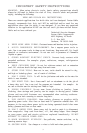
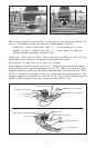
1. Loosen right fence knob (A) Fig. 14, and right fence screw (B) Fig. 14.
2. Slide the wooden fence to the right to clear bit as you move fence
assembly into the desired position front-to-back . Tighten knob (A) Fig. 14, to
secure fence assembly in position.
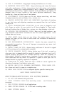
3. Position right wooden fence so that it just clears the bit path, and secure
by tightening screw (B) Fig. 14.
4. Loosen left fence knob (C) Fig. 14, and right fence screw (D) Fig. 14.
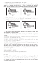
5. Slide the wooden fence to the left to clear bit as you move fence
assembly into the desired position front-to-back . Tighten knob (C) Fig. 14, to
secure fence assembly in position.
6. Position left wooden fence so that it just clears the bit path, and secure by
tightening screw (D) Fig. 14.
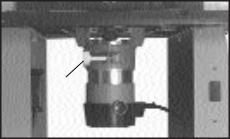
Fig. 13
A