


12
USING THE ROUTER/SHAPER
WARNING: Figures 17 and 20 through 27 show machine with cutter
guards removed for clarity. NEVER OPERATE Router/Shaper without
guards in place.
IMPORTANT: Before using your machine, consider the kind and total
amount of rnaterial to be removed. Depending on the material, it may be
necessary to make more than one cut to avoid overloading the motor.
Before beginning the cut on the actual workpiece, it is advisable to
make a sample cut on a piece of scrap lumber. This will show exactly
how the cut will look as well as enable you to check dimensions.
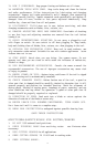
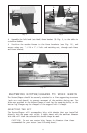
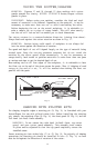
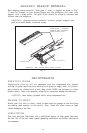
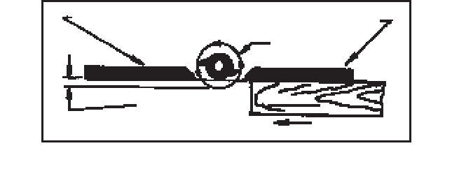
The cutter rotates in a counterclockwise direction (viewing from above).
Always feed work against the cutter rotation as shown in Fig. 17.
WARNING: Serious injury could result if workpiece is not always fed
into the cutter against the direction of rotation.
The speed and depth of cut will depend largely on the type of material being
worked upon. Keep the cutting pressure constant but do not crowd the
machine so the motor speed slows excessively. It may be necessary on
exceptionally hard woods or problem materials to make more than one pass
at various settings to get the desired depth of cut.
When making cuts on all four edges of the workpiece, it is advisable to have
the first cut on the end of the piece across the grain. Thus, if chipping of wood
occurs at the end of a cut, it will be removed when making the next cut
parallel with the grain.
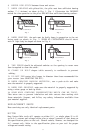
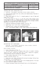
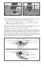
SHAPING WITH PILOTED BITS
For shaping irregular edges a starting pin (A) Fig. 19, is furnished with your
Router/Shaper for use with piloted router bits. Before installing the starting
pin, remove: the retaining clips (A) Fig. 18, the front guard (B) Fig. 18, and the
left hand (out-feed) fence assembly.
WARNING: Do not remove the right hand (in-feed) fence, top cutter
guard, and rear cutter guard assembly. This assembly must remain
in place and be adjusted so that the top guard completely covers the
installed cutter.
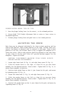
Insert starting pin into either hole (C) or (D) Fig. 19. For majority of shaping
operations the starting pin should be installed in hole (C) Fig. 19, as work
must be fed against the direction of rotation of the cutter.
Fig. 17
OUT-FEED FENCE
IN-FEED FENCE
CUTTING
CIRCLE
DEPTH OF CUT
FEED