6
CAUTION: Do not operate your tool on a current on which the
voltage is not within correct limits. Do not operate tools rated A.C.
only on D.C. current. To do so may seriously damage the tool.
EXTENSION CORD SELECTION
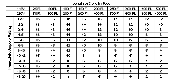
If an extension cord is used, make sure the conductor size is large enough to
prevent excessive voltage drop which will cause loss of power and possible
motor damage. A table of recommended extension cord sizes will be found in
this section. This table is based on limiting line voltage drop to 5 volts (10 volts
for 230 volts) at 150% of rated amperes.
If an extension cord is to be used outdoors it must be marked with the suffix
W-A following the cord type designation. For example SJTW-A to indicate it
is acceptable for outdoor use.
RECOMMENDED EXTENSION CORD SIZES FOR USE WITH PORTABLE ELECTRIC TOOLS
OPERATING INSTRUCTIONS
FOREWORD
Models 697 and 698 are designed to perform various shaping operations
using standard router bits.
Model 698 can be used with any Porter-Cable (or Rockwell) Professional
Router. If using Model 7538 or 7539 Plunge Router: a Model 75300 Height
Adjustment Knob must be installed and the Shaper Table must be mounted
on a Model 6961 Stand (or a cut-out table) that provides clearance for the
75300 Adjustment Knob (the knob will extend below the bottom of the
Shaper Table legs).
ASSEMBLING TABLE
1. Locate the two table legs (see Fig. 5) and stand them up parallel to each
other and approximately 12" apart. The leg with the switch mounted in it
should be to your right, with the switch facing you. Both legs should slant
toward the outside.
2. Open hardware package.
3. Place the table on top of the legs, with the miter gauge slot up and the
large hole to the rear. Secure the table to the legs with four
1
… 4-20 ¥ 1
3
… 8"
long, flat head screws, split lockwashers, and nuts.


