


1. On Models 7310 and 7319, you can install bits either with the motor unit
attached or removed.
NOTE: See the instructions (Model 7312) for installing the bit in the OFFSET
trimmer. See instructions (Model 7320) for installing the bit in the UNDERSCRIBE
trimmer.
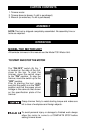
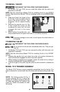
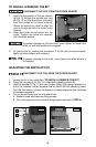
2. Clean and insert the shank of the
bit (C) Fig. 2 into the collet until the
end of the shank bottoms. Then
withdraw the bit approximately
1/16".
3. Depress the spindle lock (A) Fig.
2 and rotate the collet nut (B)
clockwise by hand until the lock
engages the hole in the motor
spindle.
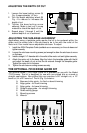
4. While holding the spindle lock, use
the provided wrench to tighten the collet nut (clockwise) securely.
10
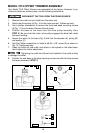
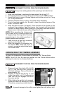
NOTE: The locking screw (A) Fig. 3
utilizes a spring (B) Fig. 3 and a flat
washer (C). Position the spring (B) with
its small end against the head of the
screw (A). Attach the washer (C) after
the spring.
TO INSTALL THE BIT
DISCONNECT THE TOOL FROM THE POWER SOURCE.
Fig. 2
A
B
C
To prevent damage to the collet, do not tighten the collet without a
bit inserted.
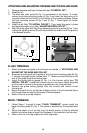
DISCONNECT THE TOOL FROM THE POWER SOURCE.
TO REMOVE THE BIT
Do not touch the trimmer bits immediately after use. They can get
very hot.
1. On Models 7310 and 7319, you can remove bits either with the motor unit
attached or removed.
NOTE: See the instructions (Model 7312) for installing the bit in the OFFSET
trimmer.
2. Depress the spindle lock and rotate the collet nut counter-clockwise by
hand until the lock engages the hole in the motor spindle.
3. While holding the spindle lock engaged, loosen the collet nut by turning it
counter-clockwise with the provided wrench.
4. If the bit is tight on the collet, tap the collet nut with a wrench to release the
bit.
MODEL 7310 TRIMMER ASSEMBLY
The Model 7310 Trimmer comes completely assembled from the factory. The
base is attached to (or removed from) the motor with a base locking screw (Fig.
3).
Fig. 3
A
B
C