


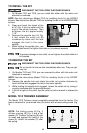

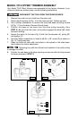
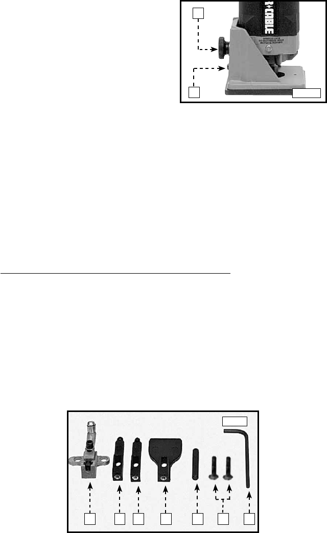
1. Loosen the base-locking screw (A)
Fig. 4) approximately 1/4 turn.
2. Turn the depth-adjusting wheel (B)
Fig. 4 to reduce or increase the
depth of cut.
3. Tighten the base-locking screw
securely. Make a test cut in scrap
material to check the depth of cut.
4. Repeat steps 1 through 3 until the
desired depth of cut is achieved.
11
ADJUSTING THE DEPTH OF CUT
A
B
Fig. 4
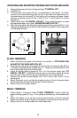
ADJUSTING THE SUB-BASE ALIGNMENT
Applications using a template guide require the bit to be centered within the
guide, and the center hole in the sub-base to be in line with the collet of the
motor unit. Your model has an adjustable sub-base. To adjust:
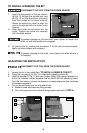
1. Install the 42054 Template Guide (available as an accessory) on the sub-base and
tighten securely.
2. Loosen the sub-base mounting screws just enough to allow the sub-base to move
on the base.
3. Install a straight 1/4" diameter bit in the collet of the motor unit and tighten securely.
4. Attach the motor unit to the base. Align the hole in the template guide with the bit
and adjust the depth of cut so that the bit extends through the template guide.
Tighten the motor unit in the base.
5. Tighten the sub-base mounting screws securely.
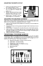
THE OPTIONAL 73100 EDGE GUIDE KIT
The optional Model 73100 Edge Guide Kit is available for use with the Model
7310 trimmer. This kit is designed for use with non-piloted bits on curved or
straight applications. Non-piloted bits can produce a 90° straight cut, a 10°
bevel cut, or a 22° bevel cut. The kit (Fig. 5) contains:
A. Base and roller guide - for flush or bevel trimming
B. Edge guide – for flush trimming
C. Edge guide – for bevel trimming
D. Straight edge guide – for straight trimming
E. Guide setting gauge
F. Mounting screws
G. Wrench
Fig. 5
A B C D E F
G