


16
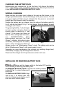
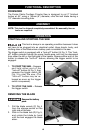
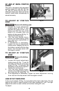
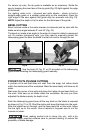
90° AND 45° BEVEL POSITIVE
STOPS
This saw is equipped with adjustable
positive stops for both 90° (N) Fig.
12, and 45° bevel cuts (O) Fig. 12.
Although these have been set at the
factory, check them occasionally to
ensure accuracy.
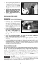
TO ADJUST 90° POSITIVE
STOP
Remove the battery pack.
1. Loosen the bevel adjustment
locking lever (K) Fig. 11 and
position the base for 90° cuts,
being sure that the top of the
base is in contact with the
bottom of stop screw (N) Fig. 12.
Tighten the locking lever.
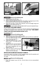
2. Turn the saw upside down,
retract the telescoping guard
and check the squareness of
blade (Fig. 13).
3. If adjustment is necessary,
loosen the bevel adjustment
locking lever, keeping the top of
the base in contact with the stop
screw. Turn the stop screw until
the angle is correct.
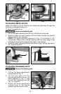
TO ADJUST 45° POSITIVE
STOP
Remove the battery
pack.
1. Loosen the bevel adjustment
locking lever (K) Fig. 11 and tilt
the base until the top of the stop
screw (O) Fig. 12 contacts the
extension on the bevel segment.
Tighten the locking lever.
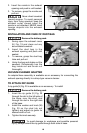
2. Turn the saw upside down,
retract the telescoping guard,
and check the 45° angle (Fig. 14).
3. If an adjustment is necessary, loosen the bevel adjustment locking
lever and turn the stop screw until the angle is correct.
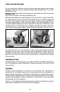
LINE OF CUT INDICATOR
A line of cut indicator (P) Fig. 15 is provided at the front of the base. The left
edge of the notch is used to follow a line when making 90° cuts. The right
edge of the notch is used to follow a line when making 45° cuts.
To adjust:
Fig. 12
NO
Fig. 13
Fig. 14