


11 - ENG N000732
OPERATION
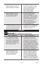
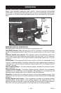
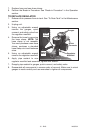
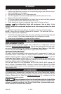
KNOW YOUR AIR COMPRESSOR
READ THIS OWNER’S MANUAL AND SAFETY RULES BEFORE OPERATING
YOURUNIT.Comparetheillustrationswithyourunittofamiliarizeyourselfwith
thelocationofvariouscontrolsandadjustments.Savethismanualforfuturerefer-
ence.
On(I)/Off(O) Switch
Safety
Valve
Tank
Pressure
Gauge
Outlet
Pressure
Gauge
Regulator
Quick
Connect
DESCRIPTION OF OPERATION
Become familiar with these controls before operating the unit.
On(I)/Off(O) Switch:PlacethisswitchintheOn(I)positiontoprovideautomatic
powertothepressureswitchandOff(O)toremovepowerattheendofeach
use.
Pressure Switch (not shown): The pressure switch automatically starts the
motor when the air tank pressure drops below the factory set "cut-in" pressure.
It stops the motor when the air tank pressure reaches the factory set "cut-out"
pressure.
Safety Valve: If the pressure switch does not shut off the air compressor at its
"cut-out" pressure setting, the safety valve will protect against high pressure by
"popping out" at its factory set pressure (slightly higher than the pressure switch
"cut-out" setting).
Tank Pressure Gauge: The tank pressure gauge indicates the reserve air pres-
sure in the tank.
Outlet Pressure Gauge: The outlet pressure gauge indicates the air pressure
available at the outlet side of the regulator. This pressure is controlled by the
regulator and is always less than or equal to the tank pressure.
Regulator:Controlstheairpressureshownontheoutletpressuregauge.Turn
regulator knob clockwise to increase pressure and counterclockwise to decrease
pressure.
Cooling System (not shown): This compressor contains an advanced design
coolingsystem.Attheheartofthiscoolingsystemisanengineeredfan.Itis
perfectly normal for this fan to blow air through the vent holes in large amounts.
You know that the cooling system is working when air is being expelled.