


20-ENG
D26998
4. When proper belt tension is achieved, tighten the remaining engine mount-
ing bolts.
5. Tighten stiffener bracket screw.
NOTE: Once the engine pulley has been moved from its factory set loca-
tion, the grooves of the flywheel and pulley must be aligned to within 1/16"
to prevent excessive belt wear. Verify the alignment by performing the fol-
lowing Pulley and Flywheel - Alignment.
Pulley and Flywheel - Alignment
The air compressor flywheel and engine pulley must be in-line (in the same
plane) within 1/16" to assure belt retention within flywheel belt grooves. To
check alignment, perform the following steps:
1. Disconnect the spark plug wire on the engine and release all air tank pres-
sure.
2. Remove belt guard.
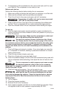
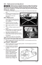
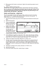
3. Place a straightedge
against the outside of
the flywheel and the
engine drive pulley.
4. Measure the distance
between the edge of
the belt and the
straightedge at points
A1 and A2 in Figure.
The difference between
measurements should be no more than 1/16".
5. If the difference is greater or less than 1/16", loosen the setscrew holding
the engine drive pulley to the shaft and adjust the pulley's position on the
shaft until the A1 and A2 measurements are within 1/16" of each other.
6. Tighten the engine drive pulley setscrew to 70-80 in.-lbs.
7. Visually inspect the engine drive pulley to verify that it is perpendicular to
the drive motor shaft. Points B1 and B2 of Figure should appear to be
equal. If they are not, loosen the setscrew of the engine drive pulley and
equalize B1 and B2, using care not to disturb the belt alignment performed
in step 2.
8. Retighten the engine drive pulley setscrew to 70-80 in.-lbs.
9. Reinstall belt guard.
10. Reconnect spark plug wire to spark plug on engine.