


7-ENG
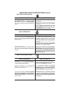
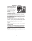
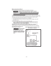
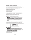
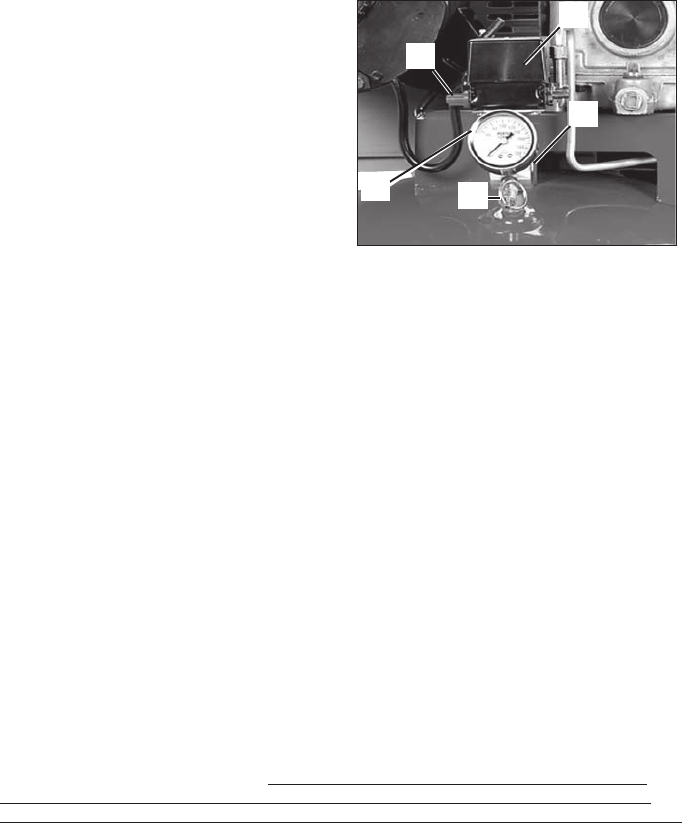
ON/AUTO-OFF Switch (A) Fig. 1: Turn
this switch ON to provide automatic
power to the pressure switch and OFF to
remove power.
Pressure Switch (B) Fig. 1: The
pressure switch automatically starts the
motor when the air tank pressure drops
below the factory set "cut-in" pressure.
It stops the motor when the air tank
pressure reaches the factory set "cut-
out" pressure.
Air Tank Safety Valve (C) Fig. 1: If the
pressure switch does not shut off the air
compressor at its cut-out pressure
setting, the safety valve will protect against high pressure by "popping off" at its
factory set pressure (slightly higher than the pressure switch cut-out setting).
Air Tank Pressure Gauge (D) Fig. 1: The air tank pressure gauge indicates the
reserve air pressure in the air tank. On units with no pressure regulator, this is also
the pressure available at the air outlet.
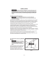
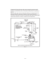
Air Intake Filter (not shown): This filter is designed to clean air coming into the
pump. This filter must always be clean and ventilation openings free from
obstructions. See "Maintenance".
Air Compressor Pump (not shown): To compress air, the pistons moves up and
down in the cylinder. On the downstroke, air is drawn in through the air intake
valves. The exhaust valve remains closed. On the upstroke of the piston, air is
compressed. The intake valves close and compressed air is forced out through the
exhaust valve, through the outlet tube, through the check valve and into the air
tank. Working air is not available until the compressor has raised the air tank
pressure above that required at the air outlet.
Drain Valve (not shown): Located at the base of the air tank to drain
condensation.
Check Valve (not shown): When the air compressor is operating, the check valve
is "open", allowing compressed air to enter the air tank. When the air compressor
reaches "cut-out" pressure, the check valve "closes", allowing air pressure to
remain inside the air tank.
Pressure Release Valve (not shown): The pressure release valve, located on the
side of the pressure switch, is designed to automatically release compressed air
from the compressor head and the outlet tube when the air compressor reaches
"cut-out" pressure or is shut off.
The pressure release valve allows the motor to
restart freely. When the motor stops running, air will be heard escaping from the
valve for a few seconds. No air should be heard leaking when the motor is running.
Shut-off Valve (sold separately): Closes the air outlet (E, Fig. 1) allowing the tank
to fill with air.
Regulator (sold separately): An air pressure regulator or a separate air
transformer which combines the functions of air regulation and/or moisture and dirt
removal is recommended for most applications.
DESCRIPTION OF OPERATION
Fig. 1
B
E
A
C
D