


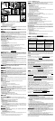

CLEARING A JAMMED NAIL (FIG. 7)
Lock off trigger, disconnect air line from tool and remove fasteners from
magazine before making adjustments or personal injury may result.
If a nail becomes jammed in the nosepiece, keep the tool pointed away from you and follow
these instructions to clear:
1. Lock off trigger.
2. Disconnect the tool from air supply.
3. Release pusher from behind nails.
4. Push down front latch (B) then pull up to open front door (R).
5. Remove bent nail, using pliers if necessary.
6. If driver blade is in the down position, insert screwdriver or other rod into nosepiece and
push driver blade back in position.
7. Remove rod and close front door.
8. Lift latch to secure door to nosepiece.
9. Reattach air supply.
10. Reinsert nails into magazine (see Loading the Tool).
11. Release pusher.
NOTE: Should nails continue to jam frequently in nosepiece, have tool serviced by an
authorized PORTER-CABLE service center.
COLD WEATHER OPERATION
When operating tools at temperatures below freezing:
1. Make sure compressor tanks have been properly drained prior to use.
2. Keep tool as warm as possible prior to use.
3. Make certain all fasteners have been removed from magazine.
4. Lower air pressure to 80 psi or less.
5. Reconnect air and and load nails into magazine.
6. Turn pressure up to operating level (not to exceed 120 psi) and use tool as normal.
7. Always drain the compressor tanks at least once a daily.
HOT WEATHER OPERATION
Tool should operate normally. However, keep tool out of direct sunlight as excessive heat
can deteriorate bumpers, o-rings and other rubber parts resulting in increased maintenance.
BELT HOOK (FIG. 8)
The PORTER-CABLE nailers include an integrated belt hook (H) and can be rotated to either
side of the tool to accommodate left- or right- handed users. It can also be rotated out of the
way when not in use.
If the hook is not desired at all, it can be removed from the tool.
To remove belt hook:
1. Lock off trigger.
2. Disconnect the tool from air supply.
3. Using the appropriate hex wrench, remove the end cap screws from the end cap (S) of
the tool.
4. Remove the belt hook.
5. Replace end cap and gasket. Ensure that the three screws are tight.
6. Replace and tighten air fitting.
MAINTENANCE
Lock off trigger, disconnect air line from tool and remove fasteners from
magazine before making adjustments or personal injury may result.
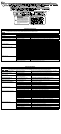
DAILY MAINTENANCE CHART
ACTION WHY HOW
Drain compressor tanks
and hoses daily.
Prevents accumulation
of moisture in com-
pressor and nailer.
Open petcocks or other
drain valves on compressor
tanks. Allow any accumulated
water to drain from hoses.
Clean magazine, pusher and
contact trip mechanism.
Permits smooth opera-
tion of magazine, reduces
wear and prevents jams.
Blow clean with compressor
air. The use of oils, lubricants
periodically or solvents is
not recommended as they
tend to attract debris.
Before each use, check
to insure all screws,
nuts and fasteners are
tight and undamaged.
Prevents jams, leaks
and premature fail-
ure of tool parts.
Tighten loose screws
or other fasteners using
the appropriate hex
wrench or screwdriver.
CLEANING
Never use solvents or other harsh chemicals for cleaning the non-metallic
parts of the tool. These chemicals may weaken the materials used in these parts. Use a
cloth dampened only with water and mild soap. Never let any liquid get inside the tool; never
immerse any part of the tool into a liquid.
REPAIRS
For assistance with your tool, visit our website at www.deltaportercable.com for a list of
service centers, or call the PORTER-CABLE Customer Care Center at (888) 848-5175.
SERVICE
REPLACEMENT PARTS
Use only identical replacement parts. For a parts list or to order parts, visit our website at
servicenet.porter-cable.com. You can also order parts from your nearest PORTER-CABLE
Factory Service Center or PORTER-CABLE Authorized Warranty Service Center. Or, you can
call our Customer Care Center at (888) 848-5175.
SERVICE AND REPAIRS
All quality tools will eventually require servicing and/or replacement of parts. For information
about PORTER-CABLE, its factory service centers or authorized warranty service centers,
visit our website at www.deltaportercable.com or call our Customer Care Center at (888) 848-
5175. All repairs made by our service centers are fully guaranteed against defective material
and workmanship. We cannot guarantee repairs made or attempted by others.
You can also write to us for information at PORTER-CABLE, 4825 Highway 45 North, Jackson,
Tennessee 38305 - Attention: Product Service. Be sure to include all of the information shown
on the nameplate of your tool (model number, type, serial number, etc.).
ACCESSORIES
Since accessories other than those offered by Porter-Cable have not been
tested with this product, use of such accessories could be hazardous. For safest operation,
only Porter-Cable recommended accessories should be used with this product.
A complete line of accessories is available from your PORTER-CABLE Factory Service Center
or a PORTER-CABLE Authorized Warranty Service Center. Please visit our Web Site www.
deltaportercable.com for a catalog or for the name of your nearest supplier.
THREE YEAR LIMITED WARRANTY
PORTER-CABLE will repair, without charge, any defects due to faulty materials or
workmanship for three years from the date of purchase. This warranty does not cover part
failure due to normal wear or tool abuse. For further detail of warranty coverage and warranty
repair information, visit www.deltaportercable.com or call (888) 848-5175. This warranty does
not apply to accessories or damage caused where repairs have been made or attempted by
others. This warranty gives you specific legal rights and you may have other rights which vary
in certain states or provinces.
In addition to the warranty, PORTER-CABLE tools are covered by our:
1 YEAR FREE SERVICE: PORTER-CABLE will maintain the tool and replace worn parts
caused by normal use, for free, any time during the first year after purchase.
90 DAY MONEY BACK GUARANTEE: If you are not completely satisfied with the
performance of your PORTER-CABLE Power Tool, Laser, or Nailer for any reason, you can
return it within 90 days from the date of purchase with a receipt for a full refund – no questions
asked.
LATIN AMERICA: This warranty does not apply to products sold in Latin America. For
products sold in Latin America, see country specific warranty information contained in the
packaging, call the local company or see website for warranty information.
To register your tool for warranty service visit our website at
www.deltaportercable.com
.
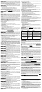
WARNING LABEL REPLACEMENT
If your warning labels (Fig. 9) become illegible or are missing, call (888) 848-5175 for a free
replacement.
ALWAYS USE SAFETY GLASSES. Everyday eyeglasses are NOT safety
glasses. Also use face or dust mask if operation is dusty. ALWAYS WEAR CERTIFIED SAFETY
EQUIPMENT:
• ANSI Z87.1 eye protection (CAN/CSA Z94.3),
• ANSI S12.6 (S3.19) hearing protection,
• NIOSH/OSHA respiratory protection.
Before operating this tool, carefully read and understand all instructions in Important
Safety Instructions.
ASSEMBLY
Lock off trigger, disconnect air line from tool and remove fasteners from
magazine before making adjustments or personal injury may result.
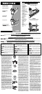
TRIGGER
Keep fingers AWAY from trigger when not driving fasteners to avoid accidental
firing. Never carry tool with finger on trigger. In bump action mode (contact actuation mode)
tool will fire a fastener if safety is bumped while trigger is depressed.
In accordance with the ANSI Standard SNT-101-2002, the PORTER-CABLE nailers are
assembled with a sequential action trigger. For a replacement trigger contact your authorized
service center or call 1-888-848-5175.
The red trigger with
imprinted on the side, (Cat.# 600852 kit) is the single sequential action
trigger and causes the tool to operate in this mode.
The black trigger with
imprinted on the side, (Cat.# 600851 kit) is the bump action trigger
and permits the tool to be actuated in this manner.
For defining the use of the sequential action trigger and bump action trigger, see the
Actuating Tool section of this manual.
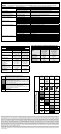
Trigger removal (Fig. 2)
1. Lock off trigger.
2. Remove air from the tool.
3. Remove rubber grommet (K) from end of dowel pin (L).
4. Remove dowel pin.
5. Remove trigger assembly from trigger cavity under the handle of the tool housing.
Trigger installation (Fig. 3)
1. Select appropriate trigger assembly to be installed on the tool.
2. Insert the trigger assembly into trigger cavity.
3. Ensure that trigger spring (M) is placed around the trigger valve stem (O).
4. Align the holes of the trigger with the housing holes (N), then insert the dowel pin (L)
through the entire assembly as shown.
5. Push the rubber grommet (K) onto the end of the dowel rod as shown.
OPERATION
PREPARING THE TOOL
Read the section titled Important Safety Instructions for Pneumatic Tools
at the beginning of this manual. Always wear eye and ear protection when operating this
tool. Keep the nailer pointed away from yourself and others. For safe operation, complete the
following procedures and checks before each use of the nailer.
NOTE: These nailers are designed to be used without oil.
1. Before you use the nailer, be sure that the compressor tanks have been properly drained.
2. Wear proper eye, hearing and respiratory protection.
3. Remove all fasteners from the magazine.
4. Check for smooth and proper operation of contact trip and pusher assemblies. Do not
use tool if either assembly is not functioning properly. NEVER use a tool that has the
contact trip restrained in the up position.
5. Check air supply. Ensure that air pressure does not exceed recommended operating
limits; 70 to 120 psi, (4.9 to 8.3 bar, 5 to 8.5 kg/cm
2
).
6. Connect air hose.
7. Check for audible leaks around valves and gaskets. Never use a tool that leaks or has
damaged parts.
To reduce the risk of personal injury, disconnect tool from air supply
before performing maintenance, clearing a jammed fastener, leaving work area, moving
tool to another location or handing the tool to another person.
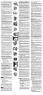
USING THE LOCK-OFF (FIG. 4)
To reduce the risk of injury, ALWAYS wear proper eye [ANSI Z87.1 (CAN/CSA
Z94.3)] and hearing protection [ANSI S12.6 (S3.19)] when operating this tool.
Do not keep trigger depressed when tool is not in use. Keep the lock-off
switch rotated to the right (OFF) when the tool is not in use. Serious personal injury may result.
Lock-off trigger, disconnect air line from tool and remove fasteners from
magazine before making adjustments. Serious personal injury may result.
Each PORTER-CABLE nailer is equipped with a trigger lock-off switch (A) which when rotated
to the right, prevents the tool from actuating. When the switch is centered, the tool will be fully
operational. The trigger should always be locked off whenever any adjustments are made or
when tool is not in use.
LOADING THE TOOL
Keep the tool pointed away from yourself and others. Serious personal injury
may result.
Never load nails with the contact trip or trigger activated. Personal injury may
result.
The PORTER-CABLE finish nailers are equipped with load and lock magazines.
Load and Lock Method (Fig. 5)
1. Lock off trigger.
2. Insert fasteners into the rear of the magazine (E).
3. Pull pusher (G) back until the nail follower falls behind the nails.
ACTUATING TOOL
To reduce the risk of injury, ALWAYS wear proper eye [ANSI Z87.1 (CAN/CSA
Z94.3)] and hearing protection [ANSI S12.6 (S3.19)] when operating this tool.
The tool can be actuated using one of two modes: single sequential action trigger mode and
bump action trigger mode. The trigger installed on the tool as described in the Trigger section
of this manual determines the mode of operation.
Sequential Action Trigger -
(red)
The sequential action trigger’s intended use is for intermittent nailing where very careful and
accurate placement is desired.
To operate the nailer in sequential action mode:
1. Depress the contact trip firmly against the work surface.
2. Depress the trigger.
A nail will fire each time the trigger is depressed as long as the contact trip
remains depressed.
Bump Action Trigger -
(black)
The bump action trigger’s intended use is for rapid nailing on flat, stationary surfaces.
Using the bump action trigger, two methods are available: place actuation and bump
actuation.
To operate the tool using the PLACE ACTUATION method:
1. Depress the contact trip against the work surface.
2. Depress the trigger.
To operate the tool using the BUMP ACTUATION method:
1. Depress the trigger.
2. Push the contact trip against the work surface. As long as the trigger is depressed, the
tool will fire a nail every time the contact trip is depressed. This allows the user to drive
multiple nails in sequence.
Do not keep trigger depressed when tool is not in use. Keep the lock-off
switch rotated to the right (OFF) when the tool is not in use.
ADJUSTING DEPTH (FIG. 6)
To reduce risk of serious injury from accidental actuation when
attempting to adjust depth, ALWAYS:
• Lock OFF trigger.
• Disconnect air supply.
• Avoid contact with trigger during adjustments.
The depth that the fastener is driven can be adjusted using the depth adjustment next to the
trigger of the tool.
1. To drive the nail shallower, rotate the depth setting wheel (F) to the right.
2. To drive a nail deeper, rotate the depth setting wheel (F) to the left.
A
N
M
O
Fig. 3
L
M
Fig. 2
K
A
Fig. 4
A
Fig. 5
E
P
Fig. 6
F
Fig. 7
B
R
Fig. 8
S
H
G
DÉTENTE À ACTION SÉQUENTIELLE
• Lorsqu’on utilise la détente par action séquentielle, ne pas actionner l’outil à
moins qu’il ne soit fermement appuyé contre la pièce.
•
RÉGLAGE DE LA PROFONDEUR : pour réduire les risques de blessures graves
lors de l’actionnement intempestif de l’outil lorsqu’on tente de régler la profondeur,
TOUJOURS :
• verrouiller la détente;
• débrancher la source d’alimentation en air;
• éviter tout contact avec la détente lors des réglages.
• Ne pas enfoncer des clous à l’aveuglette dans les murs, les planchers et autres zones
de travail. Des attaches enfoncées dans des fils électriques sous tension, de la plomberie
ou d’autres types d’obstacles peuvent entraîner des blessures. (fig. U)
• Rester vigilant, faire attention au travail en cours et faire preuve de jugement dans
l’utilisation de tout outil électrique. Ne pas utiliser d’outil en cas de fatigue ou sous
l’emprise de drogues, d’alcool ou de médicaments. Un simple moment d’inattention en
utilisant un outil électrique peut entraîner des blessures corporelles graves.
Les scies, meules, ponceuses, perceuses ou autres outils de
construction peuvent produire des poussières contenant des produits chimiques reconnus
par l’État californien pour causer cancers, malformations congénitales ou être nocifs au
système reproducteur. Parmi ces produits chimiques, on retrouve:
• le plomb dans les peintures à base de plomb;
• la silice cristallisée dans les briques et le ciment ou autres articles de maçonnerie; et
• l’arsenic et le chrome dans le bois ayant subi un traitement chimique.
Le risque associé à de telles expositions varie selon la fréquence à laquelle on effectue ces
travaux. Pour réduire toute exposition à ces produits: travailler dans un endroit bien aéré, en
utilisant du matériel de sécurité homologué tel un masque antipoussières spécialement conçu
pour filtrer les particules microscopiques.
Français continué