


14
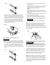
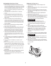
Fig. G
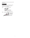
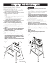
3. Tilt the table to 0° and tighten the table lock knob
(6-Fig. H). Loosen the lower blade holder lock knob
(7-Fig. G) under the table on the left side of the lower
blade holder (8-Fig. G) by turning counterclockwise.
4. Pull down on the arm, and then remove the blade
from the upper and lower blade holders by pulling
forward and lifting the blade through the access hole
(9) in the table (10). (Fig. H)
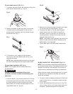
Fig. H
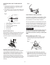
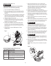
Plain-end blade installation (FIG. H, I, J)
In order to avoid uncontrollable lifting of the workpiece,
the teeth of the blade should ALWAYS point downward.
1. Install the new blade (1) through the access hole (9)
in the table (10) with teeth pointing down. (Fig. H)
2. Insert the new blade (1) into the lower blade holder
slot (11), then tighten the lower blade holder knob (7).
(Fig. I)
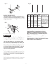
Fig. I
3. Tilt the table to 0° bevel setting and lock the bevel
knob (6). (Fig. H)
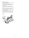
4. Insert the other end of the blade into the upper blade
holder slot (12-Fig. I) and then tighten the quick
release tension lever (14-Fig. J).
NOTE:
●
Apply slight downward pressure against the upper
arm (3) when installing the blade into the upper blade
holder. (Fig. I)
●
Clamp plain-end blades more tightly by using a hex
wrench through the screw (13).
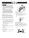
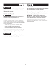
5. Tighten the tension on the blade by turning the
tension knob (15) clockwise. Check the tension on
the blade. If too loose, turn knob clockwise. (Fig. J)
Overtightening blade will cause blade breakage.
NOTE: The quick release lever must always be down
to make tension adjustments. Release the quick
release lever only during blade changing operations.
If the blade is tightened too tight, the lever will be difficult
to lower and could result in damage to the blade holder
or arm assembly.
Fig. J
PIN-END BLADE REMOVAL AND INSTALLATION
To prevent personal injury, always turn the saw
OFF and disconnect the plug from the power outlet
before changing blades or making adjustments.
Pin-end type blades are thicker for stability and faster
assembly. These blades are used whenever faster
cutting on a variety of materials and 3/4 in. (19 mm)
thickness or greater are required. Use whenever less
precision or thicker kerf cutting is acceptable.
NOTE: When installing Pin-end blades, the set screws
located on the upper and lower blade holders should
not be over or under tightened. The slot must be slightly
wider than the thickness of the blade. After the blade
is installed, the blade tension mechanism will keep the
Pin-end in place.
14
15
WARNING
!
5
3
1
4
8
7
CAUTION
12
1
4
11
7
3
13
1
6
9
10
CAUTION