


15
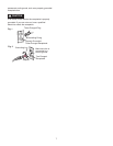
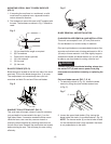
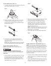
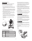
Pin-end blade removal (FIG. K, L)
1. To remove the blade, loosen the tension by lifting the
quick release tension lever (1). (Fig. K)
Fig. K
2. Remove the blade (2) from the upper (4) and lower
(5) blade holder by pulling down on the arm then
pulling forward to release, and lift the blade through
the access hole. (Fig. L)
Fig. L
3. Tilt the table to a 45° angle and lock the bevel
lock knob to view lower blade holder (5-Fig. L) for
removing the blade.
NOTE: Apply slight downward pressure on the upper
arm when removing blade from upper blade holder.
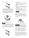
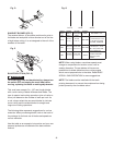
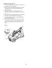
Pin-end blade installation (FIG. M, N)
NOTE: Do not tighten the lock knobs when using
Pin-end blades.
In order to avoid uncontrollable lifting of the
workpiece, the teeth of blade should always point
downward.
1. Install the blade (1) by inserting one end of it through
the access hole (2) of throat plate in the table. Hook
the lower blade pin in the pin recess in the lower
blade holder (3) and then the upper blade pin in the
upper blade holder (4). (Fig. M)
1
4
2
5
Fig. M
2. Make sure the pins are properly located in the upper
(4) and the lower (3) blade holders. (Fig. M)
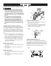
3. To tension the blade (1-Fig. M), lower the quick
release tension lever (5). Check the tension on
the blade. If tension is too tight, turn the knob (6)
counterclockwise. If tension is too loose, turn the
knob (6) clockwise (Fig. N).
NOTE: If the blade is over tightened, the lever will be
difficult to lower and could result in damage to the
blade holder or arm assembly.
4. Tighten both upper and lower
blade holder knobs.
Fig. N
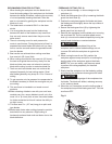
BLADE GUARD FOOT ADJUSTMENT (Fig. O, P)
NOTE: User must keep constant downward pressure
on workpiece when cutting. The blade guard foot is not
designed to hold down the workpiece, but is rather to
help prevent the workpiece from lifting up excessively.
When cutting at angles, the blade guard foot (1) should
be adjusted so it is parallel to the table and rests flat
above the workpiece.
1. To adjust, loosen the blade guard screw (2) with hex
wrench, tilt the foot so it is parallel to table and tight-
en the screw.
2. Loosen the blade guard foot lock knob (3- Fig. P) to
raise or lower the foot until it rests slightly above the
workpiece. Tighten blade guard foot lock knob.
4
1
2
3
WARNING
!
5
6