


12
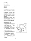
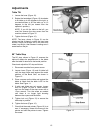
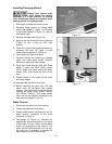
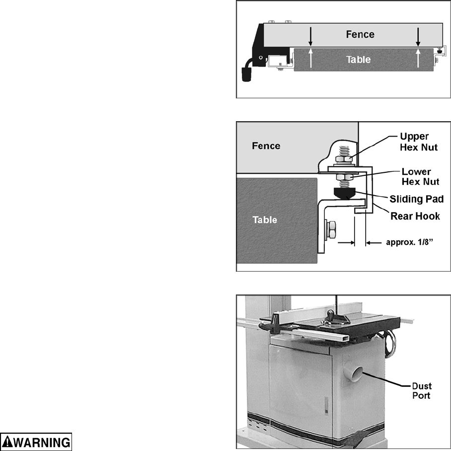
14. Check the clearance between the table and
the fence. The fence should not rub against
the table surface but be slightly above it.
This gap should be the same at the front of
the table as it is at the rear. See Figure 4.
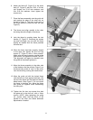
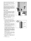
15. If the gap between fence and table is not
consistent, loosen either of the hex nuts on
the hook (Figure 5) and rotate the sliding
pad until the fence/table gap is consistent
across the full length of the table. When this
is achieved, tighten both hex nuts.
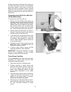
16. Check the adjustment of the hook at the
rear of the fence. The hook should be
positioned so that it overlaps the rear rail by
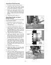
approximately 1/8”. See Figure 5. To adjust
the hook, loosen the upper hex nut (Figure
6) and slide the hook in or out as needed.
Re-tighten upper hex nut.
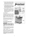
Dust Collection
The use of a dust collection system is strongly
recommended for this band saw. It will help
keep the shop clean as well as reduce any
potential health hazards caused by inhalation of
wood dust. The collector should have a capacity
sufficient for this size machine (minimum of 600
CFM).
Attach the hose of the dust collector to the 4”
dust port below the band saw table (Figure 6).
Secure with a hose clamp or duct tape.
NOTE: Dryer vent hose is not acceptable for
wood dust collection.
Grounding Instructions
Electrical connections must
be made by a qualified electrician in
compliance with all relevant codes. This
machine must be properly grounded to help
prevent electrical shock and possible fatal
injury.
This machine must be grounded. In the event of
a malfunction or breakdown, grounding provides
a path of least resistance for electric current to
reduce the risk of electric shock.
Improper connection of the equipment-
grounding conductor can result in a risk of
electric shock. The conductor with insulation
having an outer surface that is green with or
without yellow stripes, is the equipment-
grounding conductor. If repair or replacement of
the electric cord or plug is necessary, do not
connect the equipment-grounding conductor to a
live terminal.
Figure 4
Figure 5
Figure 6