


20
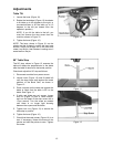
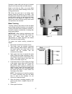
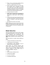
Miter Gauge
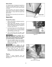
A miter gauge is provided for crosscutting
operations. Install the miter gauge by sliding the
end of the miter gauge bar into the T-slot in the
table, as shown in Figure 22.
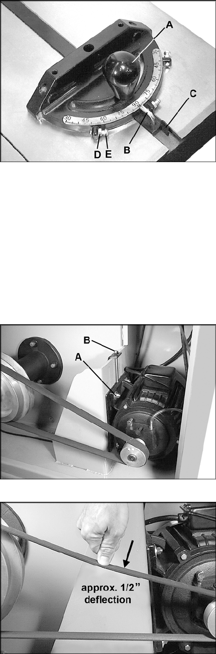
To adjust the angle of the miter gauge:
1. Loosen the handle (A, Figure 22).
2. Rotate the gauge body until the pointer (B,
Figure 22) lines up with the desired angle on
the scale. You may have to pivot the stop
(C, Figure 22) out of the way to allow the
body to rotate.
3. Tighten the handle (A, Figure 22).
4. There are three stops – at 90° and 45° left
and right. Each of these can be adjusted by
loosening the hex nut (D, Figure 22) and
turning the screw (E, Figure 22) as needed.
Re-tighten the hex nut (D, Figure 22) when
adjustment is finished.
5. Make sure the stop (C, Figure 22) is flipped
back into place.
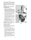
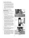
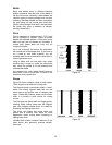
Belt Tension
The drive belt and pulleys are properly adjusted
at the factory. However, belt tension should be
occasionally checked. The belt will need to be
re-tensioned after belt replacement or changing
speeds.
1. Disconnect machine from power source.
2. Open the lower back door.
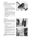
3. Loosen the four hex nuts on the motor plate
(A, Figure 23).
4. Turn the tension screw (B, Figure 23)
counterclockwise to reduce tension (for
example, to remove the belt) or clockwise to
increase the tension on the belt.
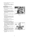
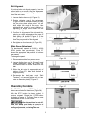
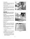
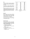
5. Check the tension by pushing down with
moderate pressure against the center of the
belt (Figure 24). An adequately tensioned
belt will deflect about 1/2”.
6. Tighten the hex nut on the tension screw (B,
Figure 23) and tighten the four hex nuts (A,
Figure 23).
NOTE: A new belt may stretch slightly during the
“breaking in” process, and the tension may need
to be checked and adjusted occasionally during
this period.
Figure 22
Figure 23
Figure 24