


6
RECEIVING THE SHAPER
Carefully unpack the shaper and any loose items from
the wood crate and inspect for damage. Any dam-
age should be reported to your distributor and ship-
ping agent immediately. Before proceeding further,
read your manual thoroughly to familiarize yourself
with proper assembly, maintenance and safety pro-
cedures.
Contents of crate:
1 shaper base
1 fence body
1 fence cover
3 table inserts
1 miter gauge rod
1 miter gauge/clamp assembly
1 spindle wrench
3 arbor wrenches
1 box containing:
1 safety shield
2 hold downs
2 fence-locking handles with washers
2 fence cover knobs
3 hold down blocks (with wing nuts)
2 aluminum fence plates
2 lock blocks with knobs
1 miter gauge bar
1 draw bar
1 cabinet handle
Remove the screws that hold the shaper to the ship-
ping crate. Remove the protective coating from the
table and loose items packed with the machine. This
coating may be removed with a soft cloth moistened
with Kerosene. DO NOT use acetone, gasoline or
lacquer thinner for this purpose. DO NOT use sol-
vents on plastic parts.
INSTALLATION
Install shaper on a level surface. Check table sur-
face with a machinist level and, if necessary, use metal
shims under low corners. Secure to the floor with
good quality anchor bolts through the holes on the
inside bottom of the base.
ELECTRICAL WIRING
WARNING: ELECTRICAL WIRING
SHOULD BE DONE BY A QUALIFIED ELECTRI-
CIAN. THE MACHINE MUST BE PROPERLY
GROUNDED TO PREVENT INJURY FROM POS-
SIBLE ELECTRIC SHOCK.
The shaper must be connected to a grounded wiring
system. See schematic, page 22 and 23.
All wiring should be done in accordance with the Na-
tional Electrical Code.
Never connect the green grounding wire to a live ter-
minal.
Make sure the voltage listed on your motor plate is
the same as that of your power source.
CAUTION: Running the motor on a lower
voltage may damage the motor.
ASSEMBLY
Tools required: set of open-end wrenches, phillips
screwdriver, spindle wrenches
FENCE ASSEMBLY
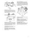
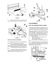
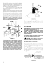
1. Mount the fence body (A) to the shaper base
(B) with the two locking handles and washers (C).
Place the cover (D) atop the fence and secure with
two knobs (E). See Figure 4.
FIGURE 4
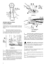
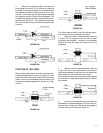
2. Attach the lock blocks (F) to the connection
plates (G) with the knobs and washers, Figure 5. Slide
the aluminum fences (H) onto the lock blocks (F) as
shown.
NOTE: The knobs are spring-loaded and can be re-
positioned without affecting the screw; simply pull up
on the handle and reposition it on the nut located be-
neath the handle.
!
!