


8
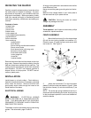
FIGURE 9
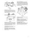
SPINDLE INSTALLATION
& REPLACEMENT
The Model 29 can use interchangeable spindles as
well as router bits. To install the spindle, proceed as
follows:
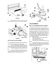
1. Disconnect machine from power source.
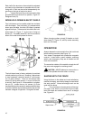
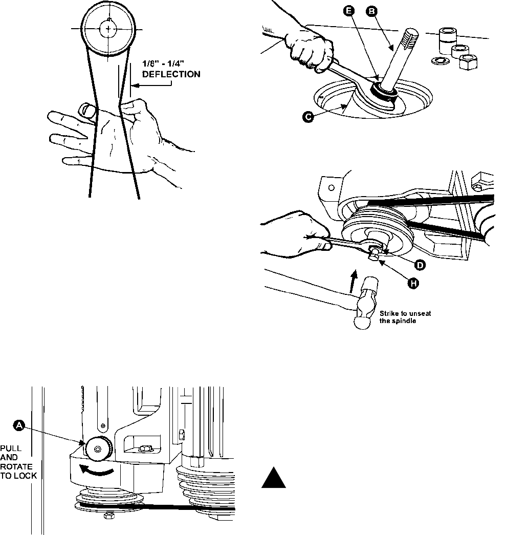
2. Lock the main shaft by opening the rear door
in the cabinet and pulling out the knob (A), Figure 10,
and rotating it to the right until it locks in place.
FIGURE 10
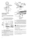
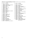
3. Make sure the spindle and bore of the main
shaft are clean of sawdust and debris.
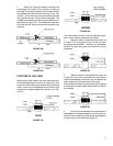
4. Insert the spindle (B) into the shaft (C), match-
ing their alignment pins, Figure 11. Then tighten up
the nut on the draw bar (D) below the pulley to seat
the spindle, Figure 12.
5. Lock the lower spindle nut with the provided
"hook"-shaped spindle wrench (E), securing it tightly,
Figure 11. (NOTE: You will have to tilt the shaft as-
sembly to use the spindle wrench).
FIGURE 11
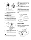
FIGURE 12
6. Unlock the shaft by rotating the lock knob
(Figure 10) to the left and allowing it to snap back in.
7. To remove a spindle, loosen the nut (E), Fig-
ure 11, then take down the nut on the draw bar (D),
Figure 12. Loosen the draw bar by turning 2 or 3
times (H), and use hammer or other hard material to
strike the base of the draw bar to unseat the spindle.
WARNING: After installing and checking the
spindle, CHECK AGAIN. Make certain the draw bar
and nut, and spindle nut, are tightened securely!
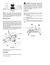
TILTING THE SPINDLE
The spindle will tilt from 5 degrees backward to 45
degrees forward. To adjust the tilt:
1. Loosen knob (G) on the tilting handwheel (H),
Figure 13.
2. Loosen lock handles (J) on both sides of the
machine.
3. Turn handwheel (H) to desired position and
tighten knob (G) and handles (J).
!