


9
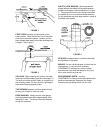
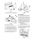
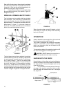
FIGURE 13
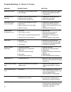
RAISING & LOWERING SPINDLE
1. Loosen the small handwheel (K), Figure 13.
2. Turn large handwheel (L) until spindle
reaches the desired height.
3. Retighten small handwheel (K).
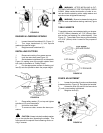
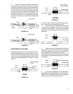
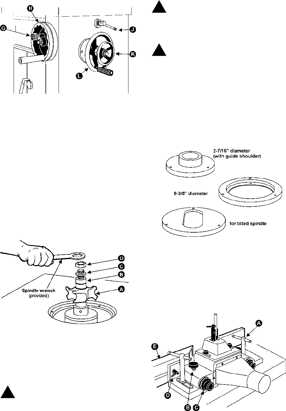
INSTALLING CUTTERS
1. Disconnect machine from power source.
2. Lock the main shaft (see Figure 10).
3. Set the desired cutterhead (A) on the spindle,
Figure 14, making sure of the proper rotation direc-
tion (refer to illustration in "Safety Rules").
4. Put the appropriate number of stacking col-
lars (B) onto the spindle to attain the proper height.
FIGURE 14
5. Place safety washer (C) on top and tighten
spindle nut (D) onto the spindle.
6. Unlock the main shaft.
7. To remove a cutter, reverse the above pro-
cedure.
CAUTION: Always include the safety washer
(C) on the spindle when operating the shaper. This
helps prevent the spindle from loosening while run-
ning in reverse.
WARNING: AFTER INSTALLING A CUT-
TER AND CHECKING IT FOR TIGHTNESS, CHECK
AGAIN! Make certain the direction of cutter is cor-
rect and that the stacking collar, safety washer and
spindle nut are all tightened securely!
WARNING: Be sure to release the lock knob
from the main shaft before starting machine (Figure
10).
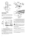
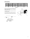
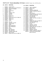
TABLE INSERTS
Three table inserts come standard with your shaper:
a 6-3/8" (160mm) diameter, a 2-7/16" (60mm) diam-
eter and an oval opening (for a tilted spindle). See
Figure 15. The smaller insert has a guide shoulder
of 3-3/16" (80mm) which is used for the purpose of
copying.
FIGURE 15
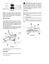
FENCE ADJUSTMENT
1. Loosen the handles (A) and move fence body
to desired position, Figure 16. Re-tighten the handles.
2. Loosen the knob (B) and turn the fence knob
(C) until correct setting is achieved.
3. Retighten knob (B).
FIGURE 16
!
!
!