


7
FIGURE 5
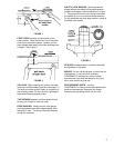
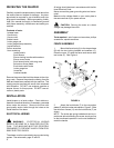
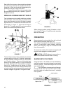
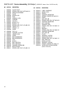
3. Mount the dust hood (J) to the rear of the
fence body (A) with the four cross screws, Figure 6.
FIGURE 6
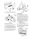
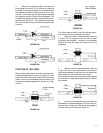
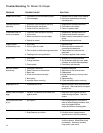
MITER GAUGE/CLAMP ASSEMBLY
The miter gauge and clamp are used for shaping the
end of stock. To assemble the miter gauge:
1. Assemble miter gauge (A) by placing bottom
screw into hole on bar (B) and screwing knob and
washer onto threaded rod (C), Figure 7. Tighten knob.
2. Slide miter gauge bar into table slot from the
end.
3. Insert rod (D) and work stop (E) into the mi-
ter gauge, making sure flat side of rod is facing up.
Tighten knobs (F) on miter gauge, Figure 7.
FIGURE 7
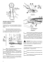
ADJUSTMENTS
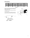
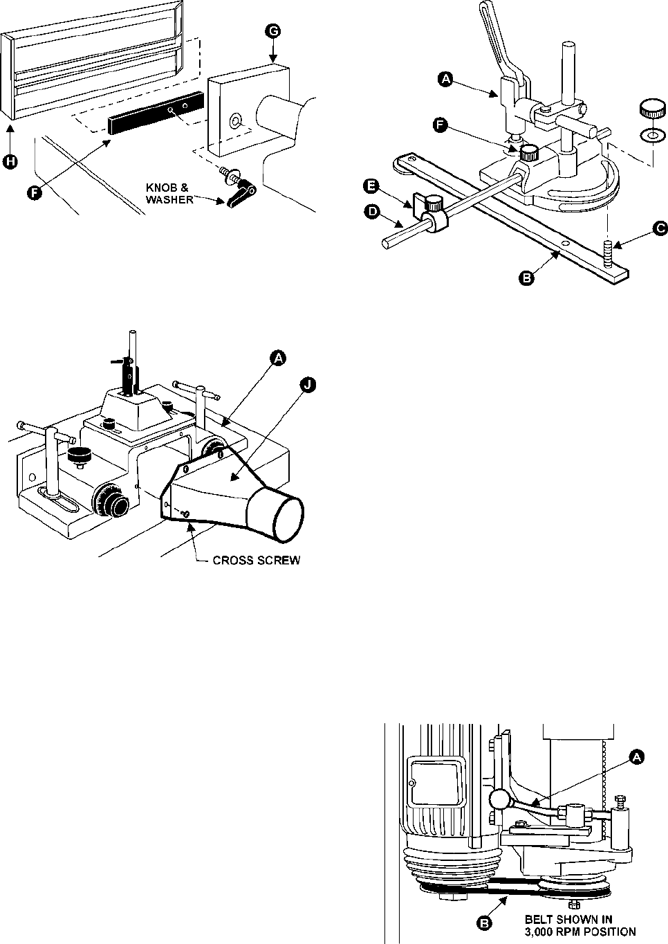
BELT ADJUSTMENT/SPEED CHANGE
The Model 29 Tilting Shaper is equipped with a mo-
tor and shaft pulley, Figure 8, capable of delivering
five speeds. Beginning with the top grooves on the
pulleys, the speeds are 10,000; 8,000; 6,000; and
4,000 RPM, down to the lowest groove which pro-
vides 3,000 RPM. A diagram found on the front of
the machine will aid in identifying these positions.
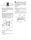
To change the speed and adjust the proper belt ten-
sion, proceed as follows:
1. Disconnect machine from power source.
2. Open front guard door.
3. Pull handle (A) to loosen belt.
4. Move belt (B) to the desired groove on the
pulleys.
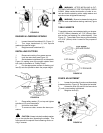
5. Adjust the belt tension, and push handle (A)
back in to retighten. Proper tension is reached when
the belt can be depressed about 1/8 inch to 1/4 inch
between the two pulleys, Figure 9.
FIGURE 8