9
Tool Support
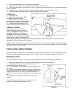
The tool support (shown in Figure 5), is designed to
allow adjustment for height, position on the bed, and
angle to the work. Your 3520A lathe comes standard
with the 14" tool support. Other supports are
available; consult the "Optional Equipment" list on
page 24.
Periodically the tool rest should be disassembled and
the parts cleaned and oiled to provide free movement
of the parts to insure good clamp action.
Spindle
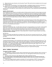
The spindle bearing preload is set at the factory for
general turning applications. There should be no "end
play" of spindle looseness along its axis. If any
looseness ever occurs it may be removed by
tightening the bearing lock nut on the left end of the
spindle. Be very careful not to overtighten the lock
nut or the spindle bearings will overheat. It should be
tightened just enough to remove the end play and the
spindle should rotate very freely.
Speed Range Adjustment
To provide the maximum horsepower to the spindle at
the very slow speeds, set the drive belt in the low
range.
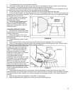
To change speed ranges, open the access door in
front of the headstock, loosen the pivot lock handle
located in the motor tension slot, raise the motor up
by lifting up on the motor plate handle and relock the
lock handle to hold the motor up. There should be
sufficient slack in the belt to reposition it to the other
step. Loosen the tension lock handle and lower the
motor to tension the belt. Be sure that the Poly-V
grooves of the belt seat properly in the corresponding
groove of the pulley. Do not overtension; a very light
pressure on the motor plate handle is adequate to
prevent belt slippage.
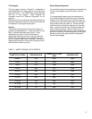
TABLE 1: WOOD TURNING LATHE SPEEDS
DIAMETER OF WORK ROUGHING RPM
GENERAL CUTTING
RPM
FINISHING RPM
Under 2" 1520 3000 3000
2 to 4" 760 1600 2480
4 to 6" 510 1080 1650
6 to 8" 380 810 1240
8 to 10" 300 650 1000
10 to 12" 255 540 830
12 to 14" 220 460 710
14 to 16" 190 400 620
16" to 20" 175 325 500
20" to 24" 175 260 400


