


13
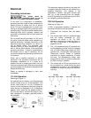
Extension Cords
The use of extension cords is discouraged. Try to
position equipment within reach of the power
source. If an extension cord becomes necessary,
make sure it is in good condition, and heavy
enough to carry the current your machine will draw.
An undersized cord will cause a drop in the line
voltage resulting in power loss and overheating.
Table 1 shows the correct size to use depending
on the cord length and nameplate ampere rating.
If in doubt, use the next heavier gauge.
Remember, the smaller the gauge number, the
heavier the cord.
Adjustments
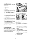
Fence Movement
The fence can be moved forward or backward
across the width of the table. It also tilts up to 45
degrees forward and has a positive stop at 90
degrees.
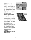
The fence assembly should periodically be moved
to different positions when edge jointing to
distribute wear on the cutterhead knives.
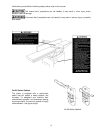
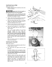
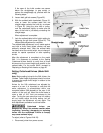
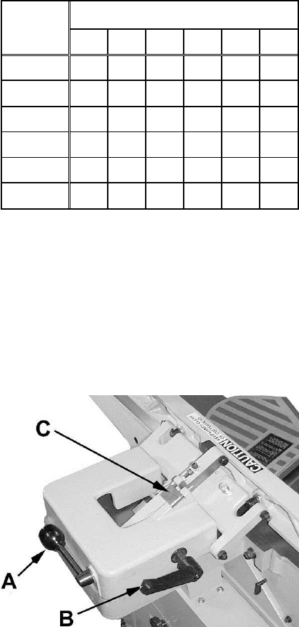
Referring to Figure 13:
To slide the fence forward or backward:
1. Loosen the lock handle (A).
2. Push the entire fence assembly to the desired
position, and tighten the locking handle.
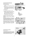
To tilt fence forward:
The fence can be tilted forward to any angle down
to 45 degrees.
1. Loosen the lock handle (B).
2. Adjust the fence to the desired level down to
45 degrees. Or you can place your reference
piece on the table and against the fence, and
adjust the fence until the angle of the fence
matches the bevel of your gauge piece.
3. Tighten lock handle (B).
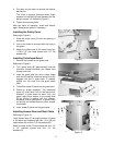
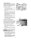
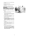
To tilt fence backward:
The fence can be tilted backward up to 45° (that is,
for a total included angle of 135° from table
surface).
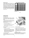
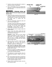
Recommended Extension Cord Gauges
Amps
Extension Cord Length in Feet *
25 50 75 100 150 200
< 5 16 16 16 14 12 12
5 to 8 16 16 14 12 10 NR
8 to 12 14 14 12 10 NR NR
12 to 15 12 12 10 10 NR NR
15 to 20 10 10 10 NR NR NR
21 to 30 10 NR NR NR NR NR
*based on limiting the line voltage drop to 5V at 150% of the
rated amperes.
NR: Not Recommended.
Table 1
Figure 13
1. Loosen lock handle (B).
2. Flip the 90° stop block (C) out of the way.
3. Adjust the fence to the desired angle up to 135
degrees. Or you can place your beveled
reference piece on the table and against the
fence, adjusting the fence until the angle of the
fence matches the bevel of your reference
piece.
5. Tighten lock handle (B).
Important: When the tilted operation is finished and
the fence is returned to 90°, do not forget to flip the
90° stop block C) back to its original position.